As we know, a potentiometer is a type of resistor whose resistance size or resistance value can be varied according to our needs. in Arduino, we can see the value generated by the Potentiometer.
I will try to read the value generated by the potentiometer, this time I will use the online learning platform Tinkercad.
Platform Online Tinker CAD
The online tinkercad platform can be used to simulate multiple control circuits. Now I will try to simulate the reading of the analog potentiometer value using the Tinkercad online platform using the Arduino controller.Arduino Specification
Microcontroller Atmega 328-P
Input Volatage 7 ~ 12 VDC
Output Volateg 5 VDC
Digital I/O 14 Pin , 6 Pin PWM
Analog Input 6 Pin
Flash Memory 32 KB 0.5 For BootLoader
EEPROM 1 KB
SRAM 1KB
CLOCK SPEED 116 MhzPotentiometer Specifications
Potensiometer 10 K
Pin 1 GND
Pin 2 Output
Pin 3 Input 3,3 ~ 6 VDCLCD 16 x 2 specifications
VCC GND
VSS +5 VDC
RS Contras Volatage
RW Register Select
EN Enable 0 = start to lactht data to LCD caracter ,1 = Disable
DB0 LSB
DB1 -
DB2 -
DB3 -
DB4 -
DB5 -
DB6 -
DB7 MSB
BPL Black Plan Light
GND GND Volatge BlacklightControl Circuit reads analog potentiometer value
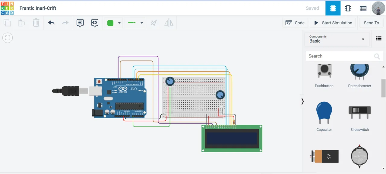
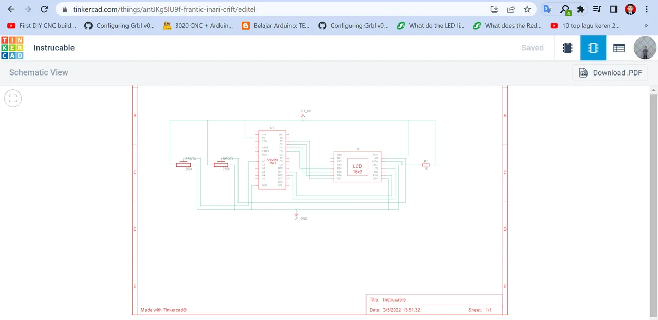
The electronic components that I will use are 2 types of potentiometers, 1 type LCD 16 x 2 and 1 Arduino R3. The circuit above is a series of simulations for reading analog values, here I will also try the Arduino program for reading analog values on the potentiometer, I will attach an example of the Arduino program below.My Program
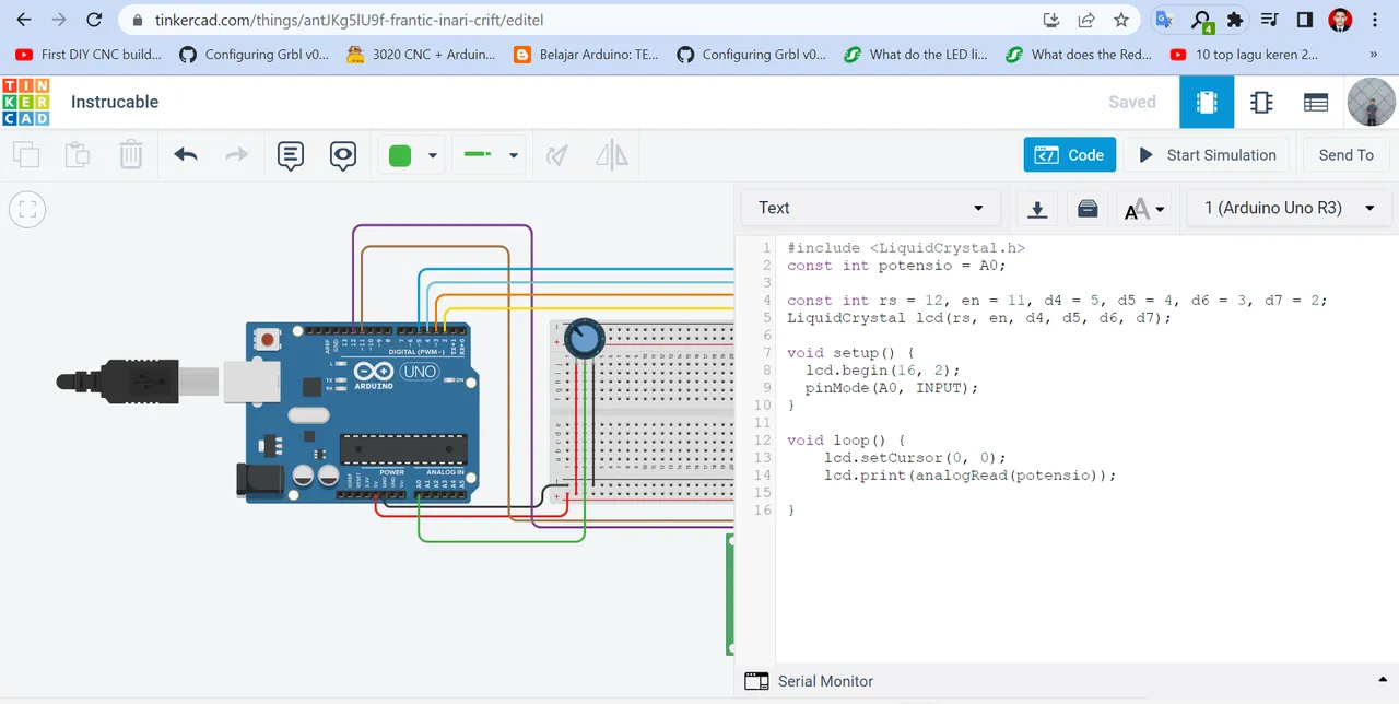
#include
const int potensio = A0;
const int rs = 12, en = 11, d4 = 5, d5 = 4, d6 = 3, d7 = 2;
LiquidCrystal lcd(rs, en, d4, d5, d6, d7);
void setup() {
lcd.begin(16, 2);
pinMode(A0, INPUT);
}
void loop() {
lcd.setCursor(0, 0);
lcd.print(analogRead(potensio));
}