As more and more design work goes digital, fewer and fewer schools teach drafting the old-fashioned way with pen paper. I would like to offer a series of posts about my board drafting tools for those who may want to use these older techniques.
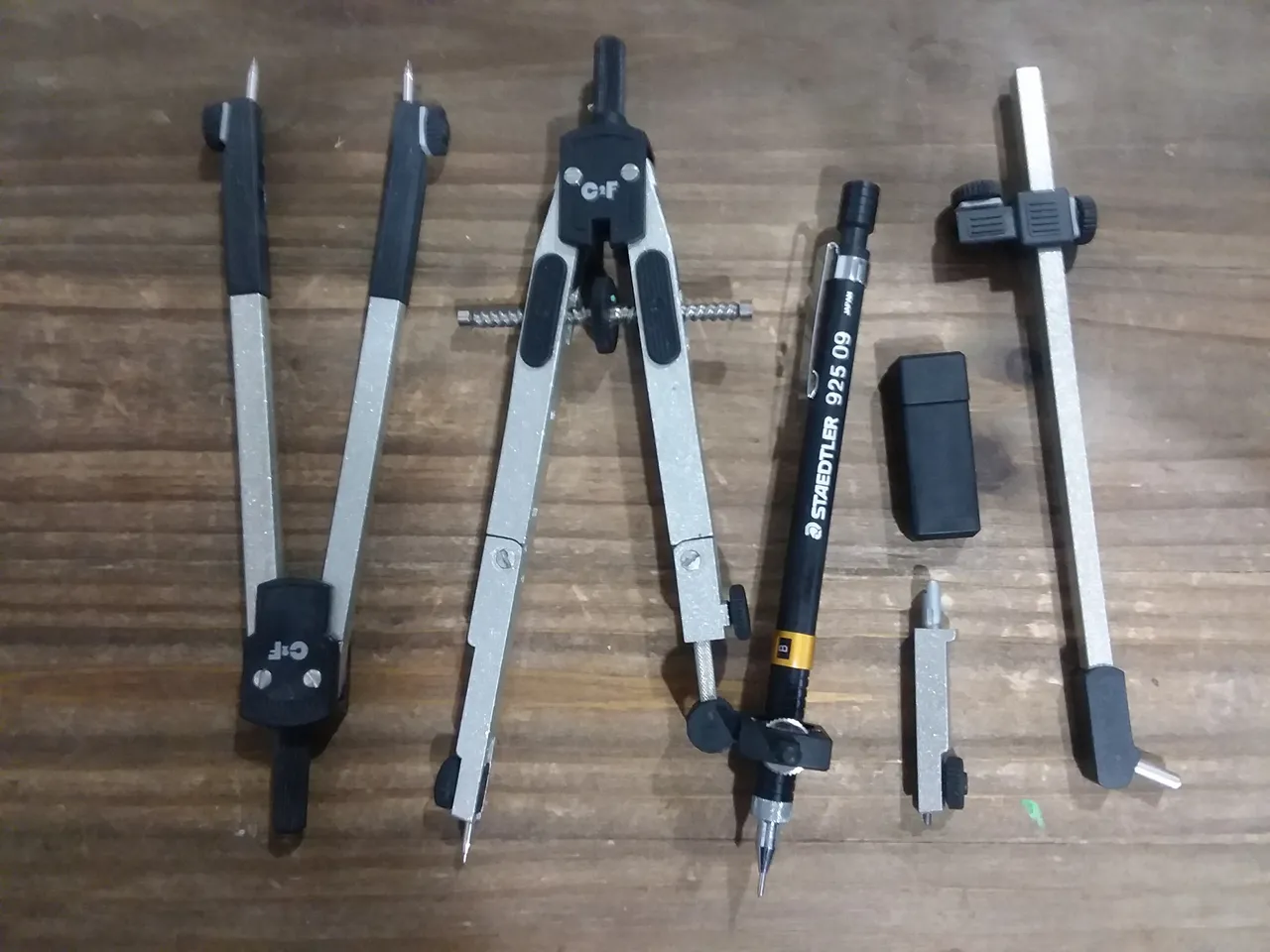
From left to right, this set includes:
- Dividers
- Compass (with pen adapter)
- Original lead scribe tip with case of spares
- Beam adapter for large radius arcs
Dividers are used to measure distances between points. Ideally, the dividers are adjusted to the length of a line on a drawing, and then held against a scale to read the measurement. In reverse, a desired length on a scale is used to set the dividers, and then they are placed on a construction line while a pencil is used to mark the endpoint. Then, a straightedge is used with a pen or pencil to draw the line. In practical use, many drafters directly measure with a scale in both instances. Perhaps I should cover scales next, or this won't make much sense. Watch for future posts in this series!
The compass quality here is higher than that of the cheap stamped metal compasses that hold a golf pencil, but I remember having problems with the joints on the compass legs slipping and messing up my work. They do, however, allow adjustment so the pen tip is perpendicular to the work surface. I should write about drafting pens and pencils at a future date, too.
The pen adapter is almost always in use when I use my compass. Swapping pens and pencils is a common task. For example, one of my pencils has blue lead that does not usually show up when a drawing is reproduced. This allows construction lines to be drawn on an original sheet without requiring erasing after the final drawing is done. Then I can switch to a pen or a pencil with dark lead to refine the segment that actually matters for the plans.
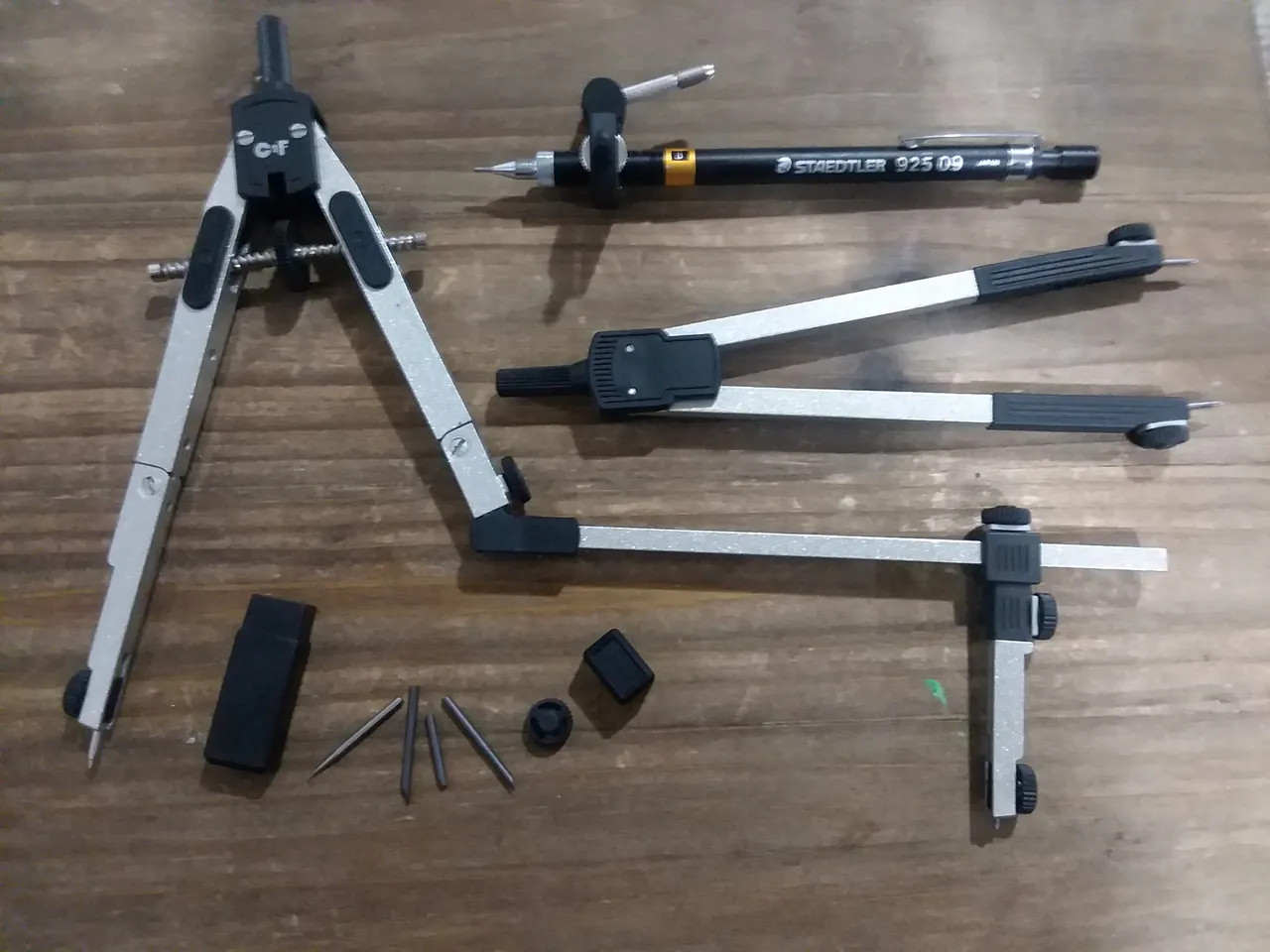
The beam compass adapter is shown above, now attached to the compass. The scribe can be moved along the length of the beam to achieve very large radii. The pen adapter could also be fitted instead of the scribe, since this set uses a common attachment system throughout. Some dedicated drafting compasses are just an adjustable beam with a fixed point at one end instead an addition to the A-frame divider-style design.
Below the compass, you can see the alternate center tip. My tools all have shouldered tips to help prevent them from making massive holes in paper should I get careless and apply too much pressure, but some drafters prefer the simpler tapered tip. I also have spare lead scribe tips and a spare tensioning knob.
The compass saw little use in architectural drafting, but mechanical drafting uses a lot of arcs to draw curved features or to construct center points for other arcs. This simple tool of ancient geometers is still used for the same kinds of work today, and if you know how to use circles and arcs to construct geometry on paper, you can easily transfer that the digital realm, too.
Please comment below if you have experience in board drafting and design, or if you have questions about anything. This is the first post in an experimental series, so clarification is doubtless necessary.

