
[Edit of Image1]
Introduction
Hey it's a me again @drifter1!
Today we continue with the Logic Design series on Verilog to get into Finite-State Machine Examples. There will be one FSM for each type (Moore, Mealy), and it will be implemented in the various ways covered in the previous part of the series.
So, without further ado, let's get straight into it!
Moore FSM Example
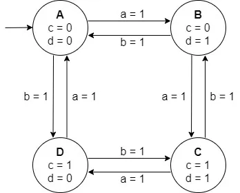
Let's consider the Moore type FSM shown below. It has 4 states, two inputs (a, b) and two outputs (c, d). When a = 1, it loops through the states in alphabetic order (A → B → C → D → A). Whilst when b = 1 it loops backwards (A → D → C → B → A). Suppose that input a has a higher priority than b.
Let's model it using:
- 2 always blocks and binary encoding
- 1 always block and one-hot encoding
Module definition
The module for the FSM can be defined as follows:
module moore_fsm (output c, d, input a, b, clk, reset);
    /* main module */
endmodule
2 always blocks and binary encoding
Let's first encode the states...
For binary encoding in order to encode 4 states at least 2 bits are needed. Using the localparam keyword, and hexadecimal number format, the declaration of the states and state registers is thus:
localparam [1 : 0] A = 'h0,
                   B = 'h1,
                   C = 'h2,
                   D = 'h3;

reg [1 : 0] state, state_next;
Let's now write the sequential section, where the state register is updated. Of course, the FSM needs to initialize to state A when the reset is active. Otherwise, the state register takes the value of the state_next register. Supposing an asynchronous and active-low reset, the always block is therefore:
always @ (posedge clk or negedge reset)
begin
    if(!reset)
        state <= A;
    else
        state <= state_next;
end
Lastly, comes the combinational section. In this section the next state logic is modeled. Because of the multiple transitions its preferable to implement it using a combinational always block with a case statement. Being a Moore FSM it's also not necessary to split this section into two always blocks: one for the next state logic and one for the output logic. The code will not become too complicated because of including it. But, spitting it is, of course, not that bad.
The combinational always block has to include the state register, and two inputs, a and b, in the sensitivity list, leading to the following code:
always @ (state or a or b)
begin
    case (state)
        A:
        begin
            if (a == 1) state_next = B;
            else if (b == 1) state_next = D;
            c = 0;
            d = 0;
        end
        B:
        begin
            if (a == 1) state_next = C;
            else if (b == 1) state_next = A;
            c = 0;
            d = 1;
        end
        C:
        begin
            if (a == 1) state_next = D;
            else if (b == 1) state_next = B;
            c = 1;
            d = 1;
        end
        D:
        begin
            if (a == 1) state_next = A;
            else if (b == 1) state_next = C;
            c = 1;
            d = 0;
        end
    endcase
end
1 always block and one-hot encoding
With one-hot encoding each bit specifies a state, thus 4 bits will be needed for the 4 states. Because only one always block will be used, only one state register is needed. Thus, the encoding section looks like this:
localparam [3 : 0] A = 4'b0001,
                   B = 4'b0010,
                   C = 4'b0100,
                   D = 4'b1000;

reg [3 : 0] state;
With a single always block the case-part of the combinational section is basically inserted into the else-part of the sequential section. This leads to the following code:
always @ (posedge clk or negedge reset)
begin
    if(!reset)
        state <= A;
    else
    begin
        case (state)
            A:
            begin
                if (a == 1) state <= B;
                else if (b == 1) state <= D;
                c = 0;
                d = 0;
            end
            B:
            begin
                if (a == 1) state <= C;
                else if (b == 1) state <= A;
                c = 0;
                d = 1;
            end
            C:
            begin
                if (a == 1) state <= D;
                else if (b == 1) state <= B;
                c = 1;
                d = 1;
            end
            D:
            begin
                if (a == 1) state <= A;
                else if (b == 1) state <= C;
                c = 1;
                d = 0;
            end
        endcase
    end
end
Mealy FSM Example
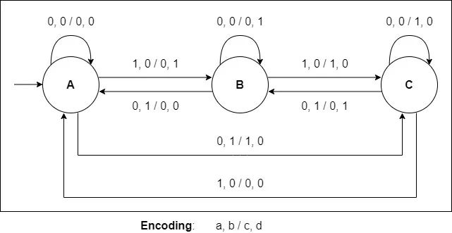
Let's now consider the Mealy type FSM shown below. It has 3 states, two inputs (a, b) and two outputs (c, d). Having a constant input of a = 1, b = 0 leads to alphabetic looping (A → B → C → A), whilst a = 0, b = 1 does it backwards (A → C → B → A).
Let's model it using:
- 3 always blocks and binary encoding
- 2 always blocks and one-hot encoding
- 1 always block and one-cold encoding
Module definition
The module for the FSM can be defined as follows:
module mealy_fsm (output c, d, input a, b, clk, reset);
    /* main module */
endmodule
3 always blocks and binary encoding
To encode 3 states in binary encoding only 2 bits are needed. Let's start from "01" instead of "00". Using the localparam keyword, the declaration of the states and state registers is thus:
localparam [1 : 0] A = 2'b01,
                   B = 2'b10,
                   C = 2'b11;

reg [1 : 0] state, state_next;
Supposing an asynchronous and active-low reset the sequential section (state register update) is the same as in the Moore example:
always @ (posedge clk or negedge reset)
begin
    if(!reset)
        state <= A;
    else
        state <= state_next;
end
First let's split the next state logic and output logic sections into two different combinational always blocks.
Let's start with the output logic. It's a simple always block with a case statement and the state register and inputs a and b in the sensitivity list:
always @ (state or a or b)
begin
    case (state)
    A:
    begin
        if (a == 0) && (b == 0)
        begin
            c = 0;
            d = 0;
        end
        else if (a == 1) && (b == 0)
        begin
            c = 0;
            d = 1;
        end
        else if (a == 0) && (b == 1)
        begin
            c = 1;
            d = 0;
        end
    end
    B:
    begin
        if (a == 0) && (b == 0)
        begin
            c = 0;
            d = 1;
        end
        else if (a == 1) && (b == 0)
        begin
            c = 1;
            d = 0;
        end
        else if (a == 0) && (b == 1)
        begin
            c = 0;
            d = 0;
        end
    end
    C:
    begin
        if (a == 0) && (b == 0)
        begin
            c = 1;
            d = 0;
        end
        else if (a == 1) && (b == 0)
        begin
            c = 0;
            d = 0;
        end
        else if (a == 0) && (b == 1)
        begin
            c = 0;
            d = 1;
        end
    end
    endcase
end
A quite similar always block is also needed for the next state logic, where the case code of course changes correspondingly. More specifically, the code is:
always @ (state or a or b)
    begin
        case (state)
        A:
        begin
            if (a == 0) && (b == 0)
                state_next = A;
            else if (a == 1) && (b == 0)
                state_next = B;
            else if (a == 0) && (b == 1)
                state_next = C;
        end
        B:
        begin
            if (a == 0) && (b == 0)
                state_next = B;
            else if (a == 1) && (b == 0)
                state_next = C;
            else if (a == 0) && (b == 1)
                state_next = A;
        end
        C:
        begin
            if (a == 0) && (b == 0)
                state_next = C;
            else if (a == 1) && (b == 0)
                state_next = A;
            else if (a == 0) && (b == 1)
                state_next = B;
        end
        endcase
    end
2 always blocks and one-hot encoding
One-hot encoding 3 states looks like this:
localparam [2 : 0] A = 3'b001,
                   B = 3'b010,
                   C = 3'b100;

reg [2 : 0] state, state_next;
The sequential section is the same as with 3 always blocks, so let's skip it.
Combining the two combinational sections, yields the following code:
always @ (state or a or b)
    begin
        case (state)
        A:
        begin
            if (a == 0) && (b == 0)
            begin
                state_next = A;
                c = 0;
                d = 0;
            end
            else if (a == 1) && (b == 0)
            begin
                state_next = B;
                c = 0;
                d = 1;
            end
            else if (a == 0) && (b == 1)
            begin
                state_next = C;
                c = 1;
                d = 0;
            end
        end
        B:
        begin
            if (a == 0) && (b == 0)
            begin
                state_next = B;
                c = 0;
                d = 1;
            end
            else if (a == 1) && (b == 0)
            begin
                state_next = C;
                c = 1;
                d = 0;
            end
            else if (a == 0) && (b == 1)
            begin
                state_next = A;
                c = 0;
                d = 0;
            end
        end
        C:
        begin
            if (a == 0) && (b == 0)
            begin
                state_next = C;
                c = 1;
                d = 0;
            end
            else if (a == 1) && (b == 0)
            begin
                state_next = A;
                c = 0;
                d = 0;
            end
            else if (a == 0) && (b == 1)
            begin
                state_next = B;
                c = 0;
                d = 1;
            end
        end
        endcase
    end
1 always block and one-cold encoding
One-cold encoding 3 states looks like this:
localparam [2 : 0] A = 3'b110,
                   B = 3'b101,
                   C = 3'b011;

reg [2 : 0] state;Inserting the case of the "combined" combinational section into the else part of the sequential section gives us the unified always block implementation:
always @ (posedge clk or negedge reset)
begin
    if(!reset)
        state <= A;
    else
    begin
        case (state)
            A:
            begin
                if (a == 0) && (b == 0)
                begin
                    state <= A;
                    c = 0;
                    d = 0;
                end
                else if (a == 1) && (b == 0)
                begin
                    state <= B;
                    c = 0;
                    d = 1;
                end
                else if (a == 0) && (b == 1)
                begin
                    state <= C;
                    c = 1;
                    d = 0;
                end
            end
            B:
            begin
                if (a == 0) && (b == 0)
                begin
                    state <= B;
                    c = 0;
                    d = 1;
                end
                else if (a == 1) && (b == 0)
                begin
                    state <= C;
                    c = 1;
                    d = 0;
                end
                else if (a == 0) && (b == 1)
                begin
                    state <= A;
                    c = 0;
                    d = 0;
                end
            end
            C:
            begin
                if (a == 0) && (b == 0)
                begin
                    state <= C;
                    c = 1;
                    d = 0;
                end
                else if (a == 1) && (b == 0)
                begin
                    state <= A;
                    c = 0;
                    d = 0;
                end
                else if (a == 0) && (b == 1)
                begin
                    state <= B;
                    c = 0;
                    d = 1;
                end
            end
        endcase
    end
endRESOURCES:
References
- http://www.asic-world.com/verilog/veritut.html
- https://www.chipverify.com/verilog/verilog-tutorial
- https://www.javatpoint.com/verilog
Images
Block diagrams and other visualizations were made using draw.io
Previous articles of the series
- Verilog Introduction → Basic Syntax, Data Types, Operators, Modules
- Combinational Logic in Verilog → Assign Statement, Always Block, Control Blocks, Gate-Level Modeling and Primitives, User-Defined Primitives
- Combinational Logic Examples → One Circuit - Four Implementations, Encoder, Decoder, Multiplexer
- Sequential Logic → Procedural Blocks (Initial, Always), Blocking and Non-Blocking Assignments, Statement Groups
- Sequential Logic Examples in Verilog → Flip Flops (DFF, TFF, JKFF, SRFF), N-bit Counter, Single-Port RAM
- Finite-State Machines in Verilog → Finite-State Machine (FSM), FSM Types, State Encoding, Modeling FSMs in Verilog
Final words | Next up
And this is actually it for today's post!
Next time we will get into Testbenches and Simulation...
See Ya!

Keep on drifting!