So in this second part of this build, I will be going through the first prototype. This will show the following
- Prototype expectation
- How to create the circuit and how the components work/ what they do.
- Details on the code behind it
- Demonstration of the working prototype.
I wont be going through the setup of the Arduino and how to install the Arduino Sketch program for coding. All of that information is on the Arduino site.
What will the prototype do.
The intention is to be able to push a button and have the Arduino control 3 LEDs; one to signify the water drop, one to signify the camera shutter and one to signify the flash firing. These should be in the correct sequence and the timings defined in the code (for now anyway; soon i'll be creating the LCD menu system for easier config). For the purposes of demonstration, the timings will be slowed down considerably.
The circuit
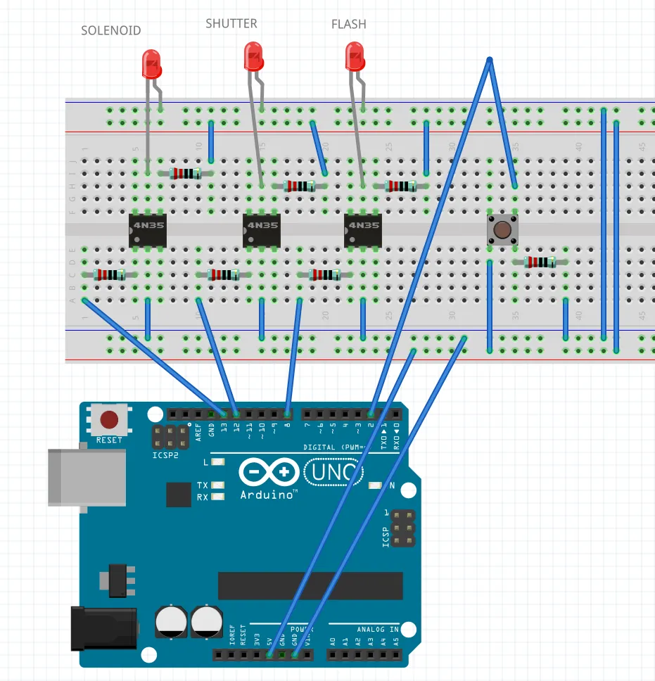
This circuit diagram was created in Fritzing
I'll try to give a brief and understandable overview of what is going on here.
On the Arduino the following pins are used
- 13 is used to fire the solenoid (OUTPUT)
- 12 is used to fire the camera shutter (OUTPUT)
- 8 is used to fire the flash (OUTPUT)
- 2 is used to detect when the button is pushed (INPUT)
- 5v and GND are the 5 volt and ground
There are 3 identical optocoupler (4N35)/LED circuits. Think of the optocoupler as a switch. When output 13 on the Arduino (for example) is put HIGH, power goes through the 330Ω resistor (which protects the LED inside the octo-coupler from too high a current). Pin 1 (bottom left) of the octo-coupler is raised and creates the circuit back to GND via Pin 2. With that circuit complete, the octo-coupler closes the circuit across pins 4 and 5 at the top using it's clever internal LED mechanism. This then closes the main LED circuit at the top of the board and the LED lights up.
The button is connected using a pull down resistor This prevents a signal being sent to the Arduino unless the button is pressed. Once the button is pressed, a high signal is sent to input 2 on the Arduino and the code acts on this
The Code
/*
 Waterdrop

 Allows the dropping of water and the firing of a flashgun / camera shutter at specific times
*/


const int buttonPin = 2;
const int waterPin = 13;
const int shutterPin = 8;
const int flashPin = 12;


int buttonState = 0;                // variable for reading the pushbutton status
int buttonDown = 0;

const int dropTime = 300;           // how long to open the solenoid in order to get a drop
const int shutterDelay = 100;       // how long in MS after the dropTime that you should fire the shutter;
const int shutterOpenTime = 350;    // how long to keep the shutter open for in ms
const int flashDelay = 350;         // how long after the water drop should the flash fire. Must be more than the shutter
const int flashSwitchTime = 10;     // the amount of time that the flashgun needs a high signal to fire

// the setup function runs once when you press reset or power the board
void setup() {
  pinMode(waterPin, OUTPUT);
  pinMode(shutterPin, OUTPUT);
  pinMode(flashPin, OUTPUT);
  pinMode(buttonPin, INPUT);
}

// main process function
void doDrop() {

  digitalWrite(waterPin, HIGH);     // open the solenoid
  delay(dropTime);                  // wait for the water to form
  digitalWrite(waterPin, LOW);      // close the solenoid

  delay(shutterDelay);              // wait to fire the shutter

  digitalWrite(shutterPin, HIGH);   // fire the shutter
  delay(flashDelay - shutterDelay); // wait to fire the flash
  digitalWrite(flashPin, HIGH);     // fire the flash
  delay(flashSwitchTime);
  digitalWrite(flashPin, LOW);      // reset flash pin
  delay(shutterOpenTime - (flashDelay - shutterDelay) - flashSwitchTime);
  digitalWrite(shutterPin, LOW);    // close the shutter


}
// the loop function runs over and over again forever
void loop() {

  buttonState = digitalRead(buttonPin);

 if (buttonState == HIGH) {
    buttonDown = 1;
  } else {
    if (buttonDown == 1)
    {
      buttonDown == 0;
      delay(1000);
      doDrop();

    }
    buttonDown=0;
  }


}
So the loop function runs forever, waiting for the state of the button to change. Once the button is pressed and released, there is a 1 second delay and the `doDrop` method is called. This runs through the steps detailed in the code and should be self explanatory
For the following demonstration, I have increased the timings to make it obvious what is happening. Red LED is the water being dropped, white is the shutter and blue is the flash going off.
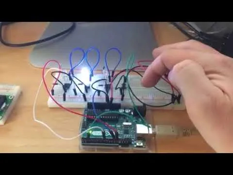
Pretty straightforward stuff but quite easy to see what is going on. Now all i have to do is switch out the LEDs with the correct components when they arrive and we will be golden (hopefully)
While I am waiting for that, i'll be working on trying to get an LCD menu system up and running so that I can change the values on the fly.
Thanks for reading
Mark