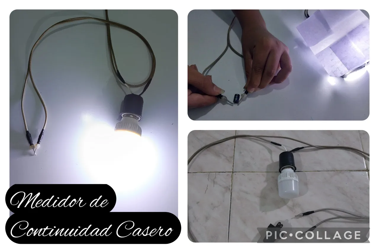
Hola amigos de la comunidad Diyhub, ¿cómo están? Dios les bendiga. Espero que se encuentren muy bien y que la paz de Dios esté sobre cada uno de ustedes. En esta oportunidad les quiero compartir algo que hice recientemente. Es un "Medidor de Continuidad Casero". No sé si a ustedes, pero a mí muchas veces me pasa que necesito comprobar el estado de un cable, el estado de un capacitador, de una resistencia, de un condensador o de un encendedor, y bueno, infinidades de componentes que digamos que los utilizo prácticamente en mi día a día. Normalmente uno utiliza un multímetro o un tester como se conoce comúnmente, pero en esta ocasión les quiero compartir un Medidor de Continuidad Casero el cual se puede elaborar con cosas que tengan a la mano en casa.
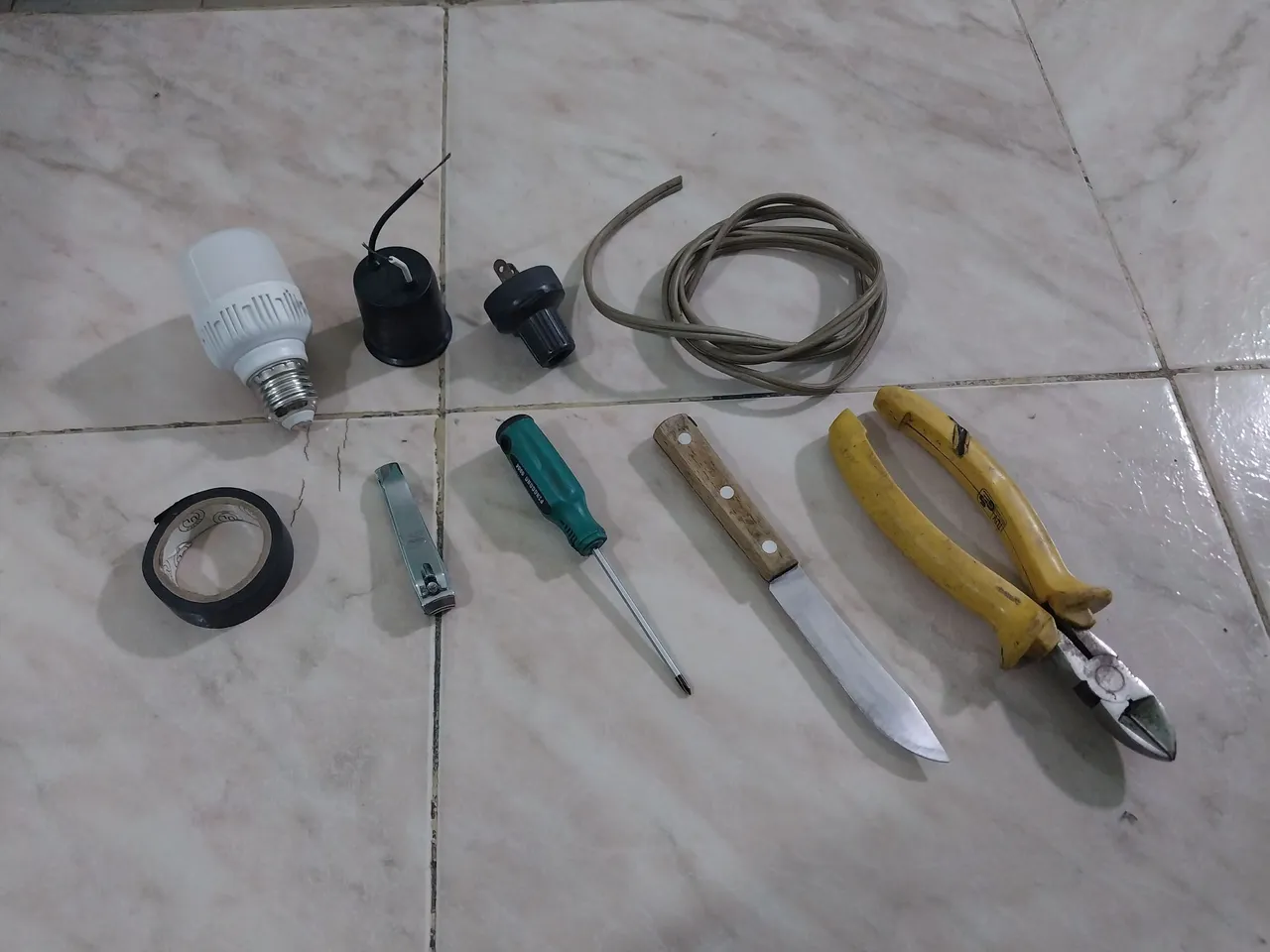
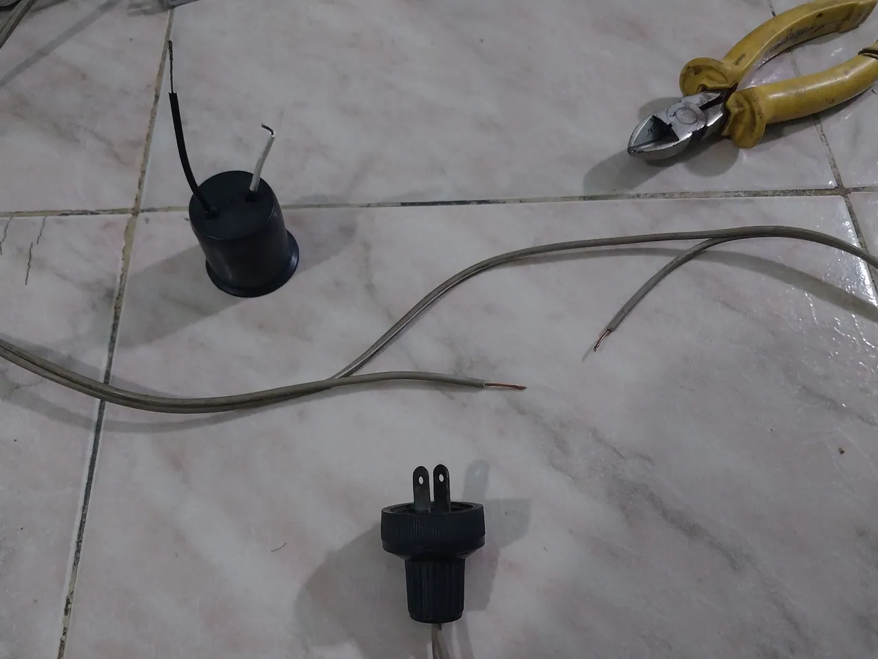
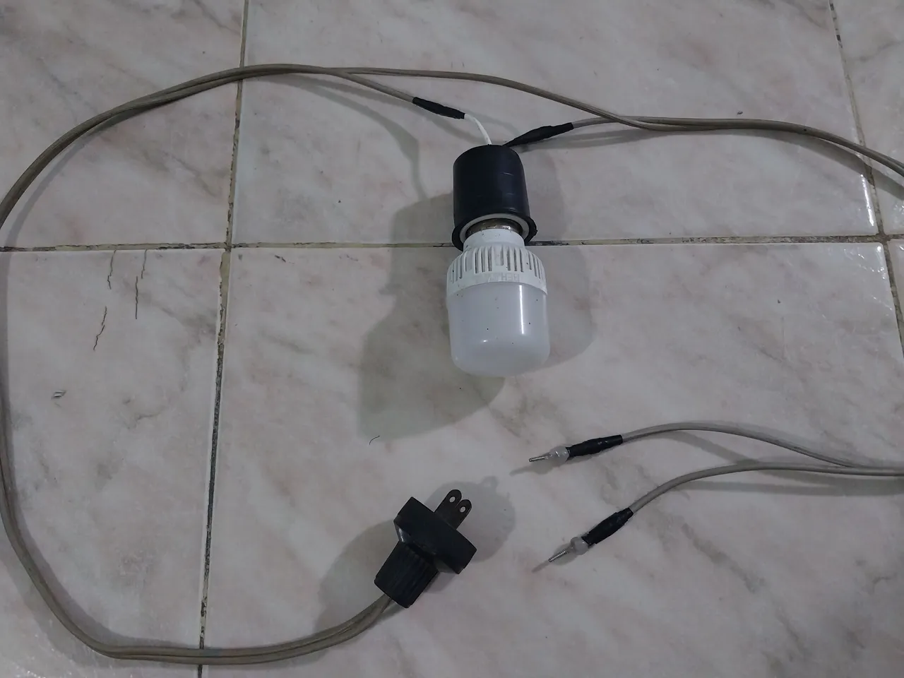
Lo primero es ubicar los materiales; para su fabricación utilice un bombillo, un socate, un enchufe, un pedazo de cable, teipe negro, un corta uñas, un destornillador de estría, un cuchillo, y una pinza.
Hello friends of the Diyhub community, how are you? God bless you. I hope you are all doing well and that God's peace be upon each of you. This time, I want to share something I recently made. It's a "Homemade Continuity Meter." I don't know about you, but I often need to check the condition of a cable, a capacitor, a resistor, a condenser, a lighter, and well, countless components that I use practically every day. Normally, one uses a multimeter or a tester, as they are commonly known, but this time, I want to share a Homemade Continuity Meter with you, which can be made with things you have on hand at home.
The first thing is to gather the materials; to make them, use a light bulb, a socket, a piece of wire, black tape, nail clippers, a slotted screwdriver, a knife, and pliers.
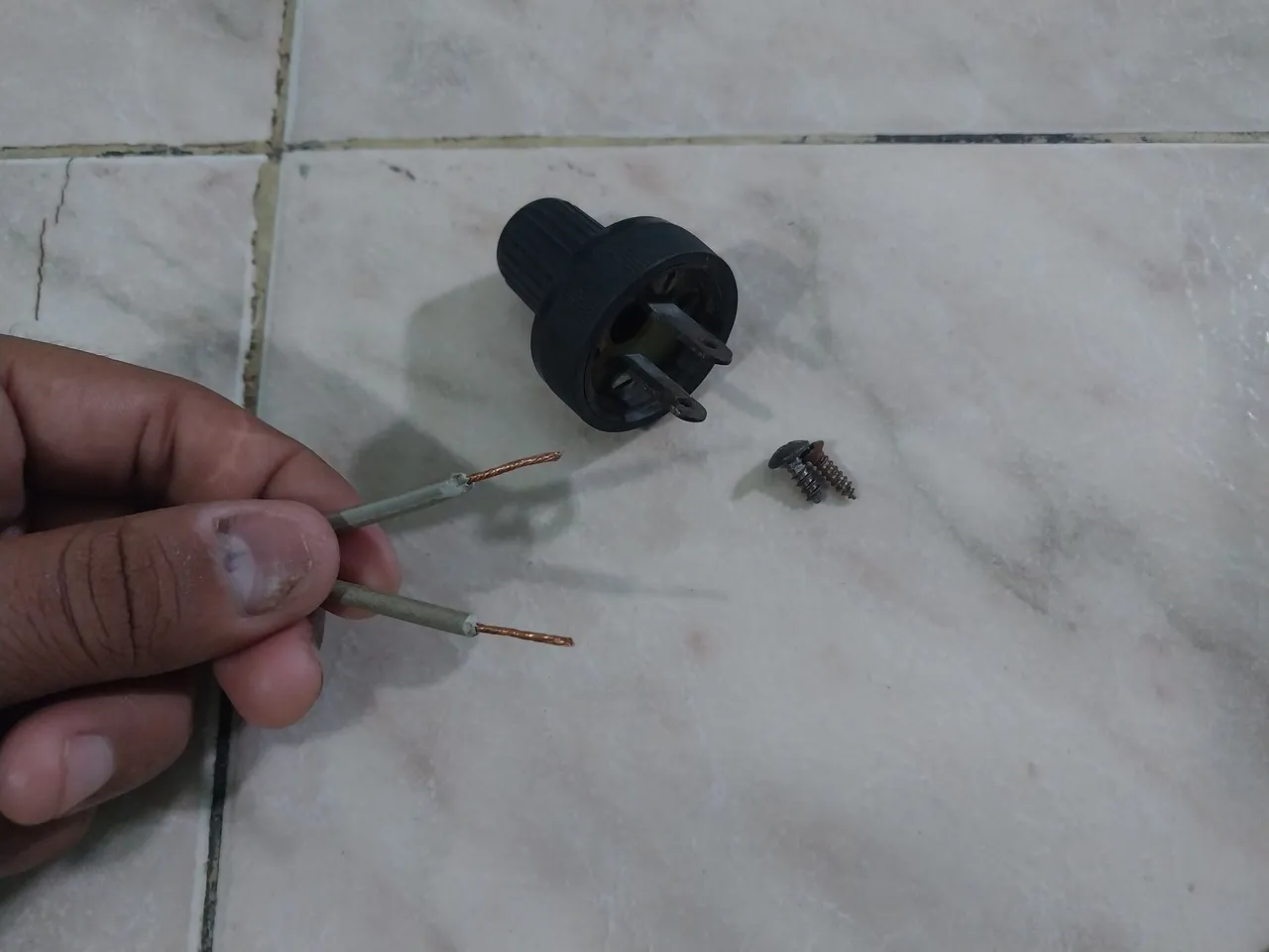
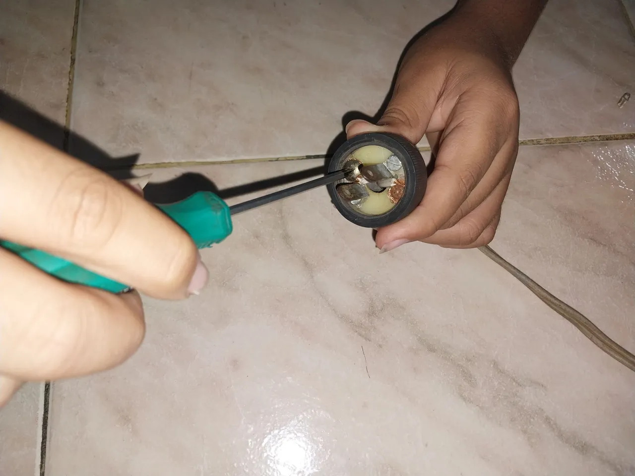
Luego de tener los materiales a la mano empecé, lo primero que hice fue ir a uno de los extremos del cable y con ayuda de la tenaza y del cuchillo retire el plástico protector de ambas puntas, y al tener el cobre procedí a instalarlo en el enchufe, luego de acomodar bien el cobre entre los tornillos y el enchufe apreté con el destornillador de manera que quedase bien ajustado y que no se fuera a mover para que no fuera a generar un cortocircuito.
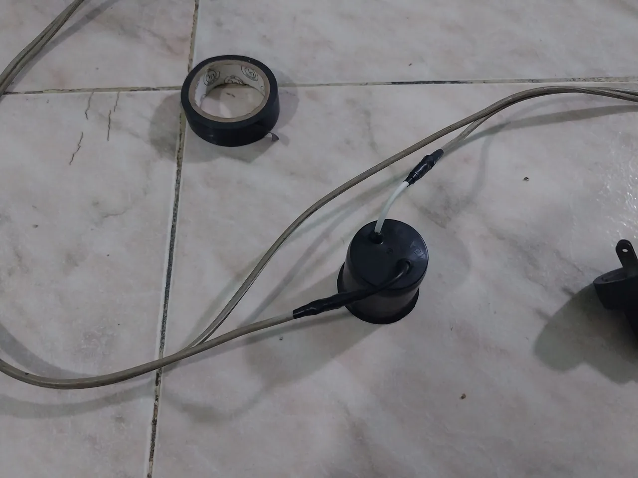
Luego de eso procedí a irme al centro del cable y corté una de las vías, luego de tener ambas puntas disponibles en la misma vía quité el recubrimiento de plástico de ambas puntas en esa línea y luego procedí a colocar el socate, hice el empalme del cobre en ambas puntas y luego de eso lo recubrí con teipe para asegurar que quede bien y evitar cualquier corto circuito.
After having the materials on hand, I began. The first thing I did was go to one end of the cable and, using pliers and a knife, remove the protective plastic from both ends. Once I had the copper wire, I proceeded to install it in the socket. After fitting the copper wire between the screws and the socket, I tightened it with the screwdriver so that it fit snugly and wouldn't move, thus preventing a short circuit.
After that, I proceeded to the center of the cable and cut one of the conductors. After having both conductors available on the same conductor, I removed the plastic covering from both ends along that line and then proceeded to place the socket. I spliced the copper wire at both ends and then covered it with tape to ensure a proper fit and prevent any short circuits.
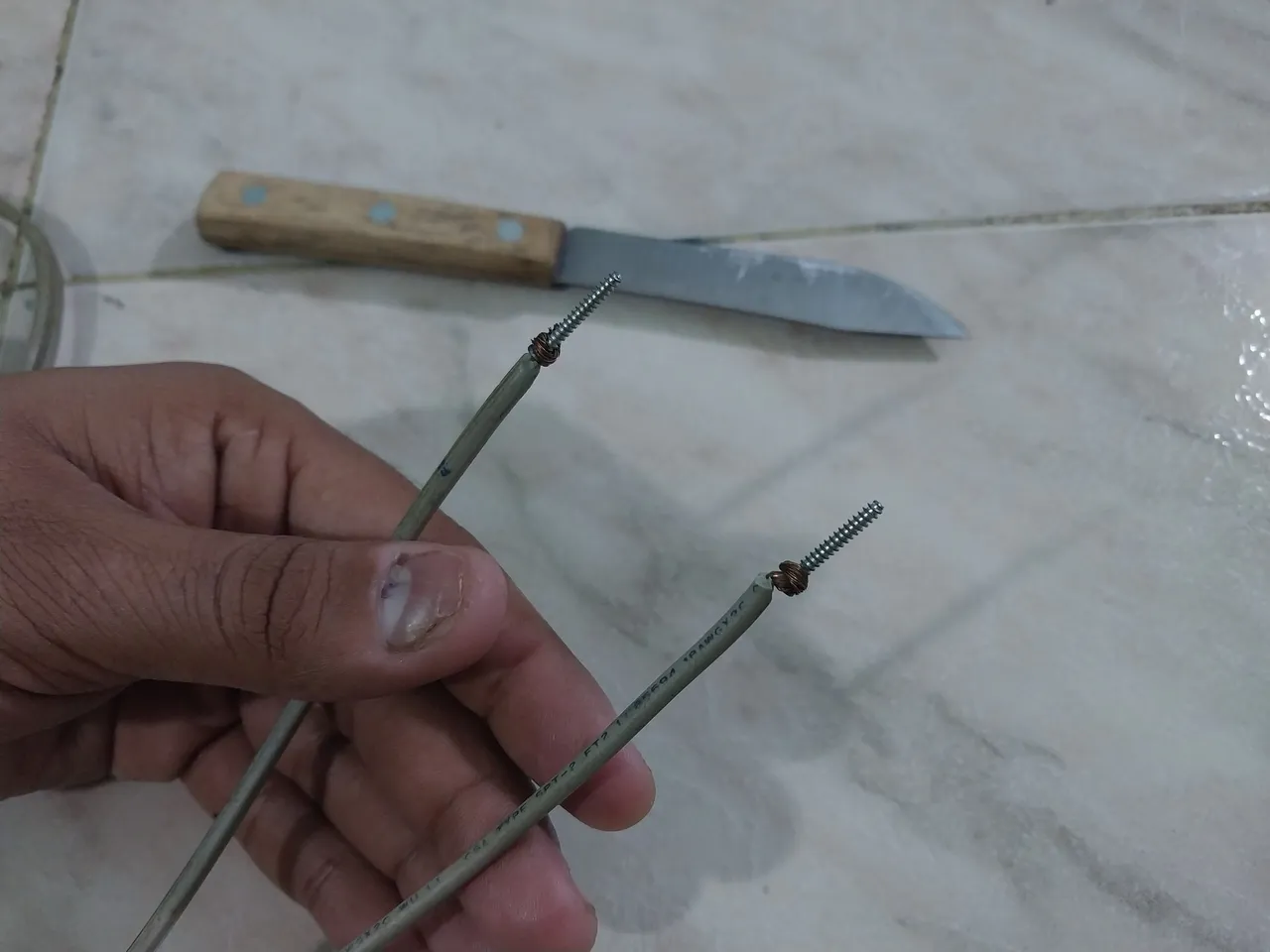
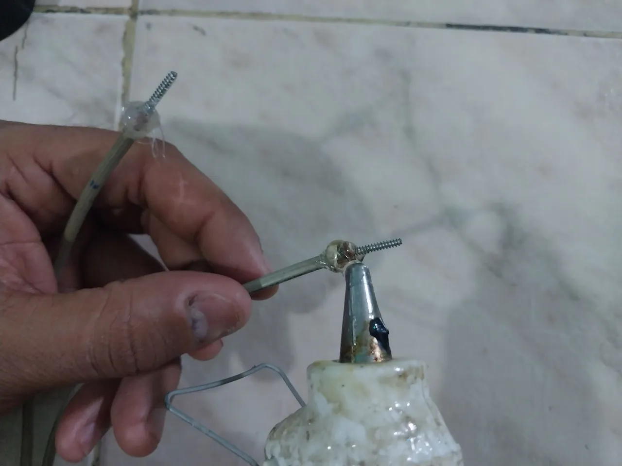
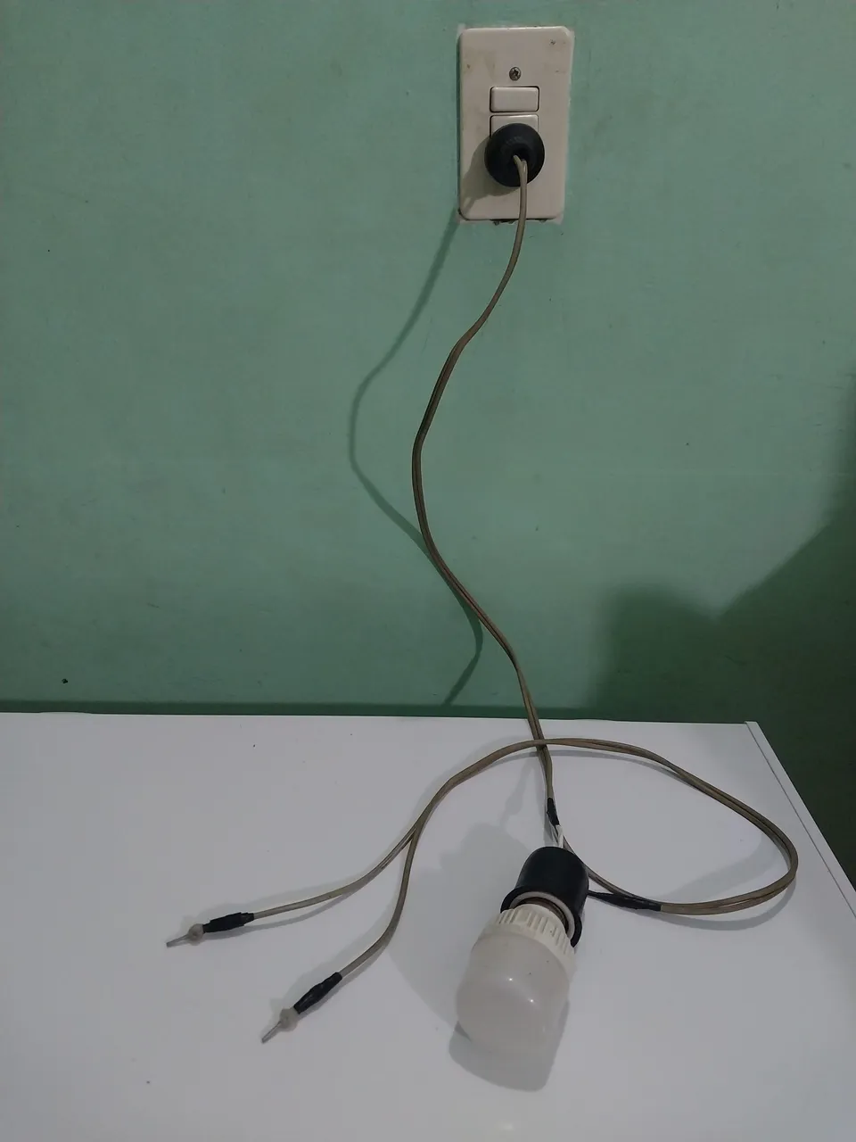
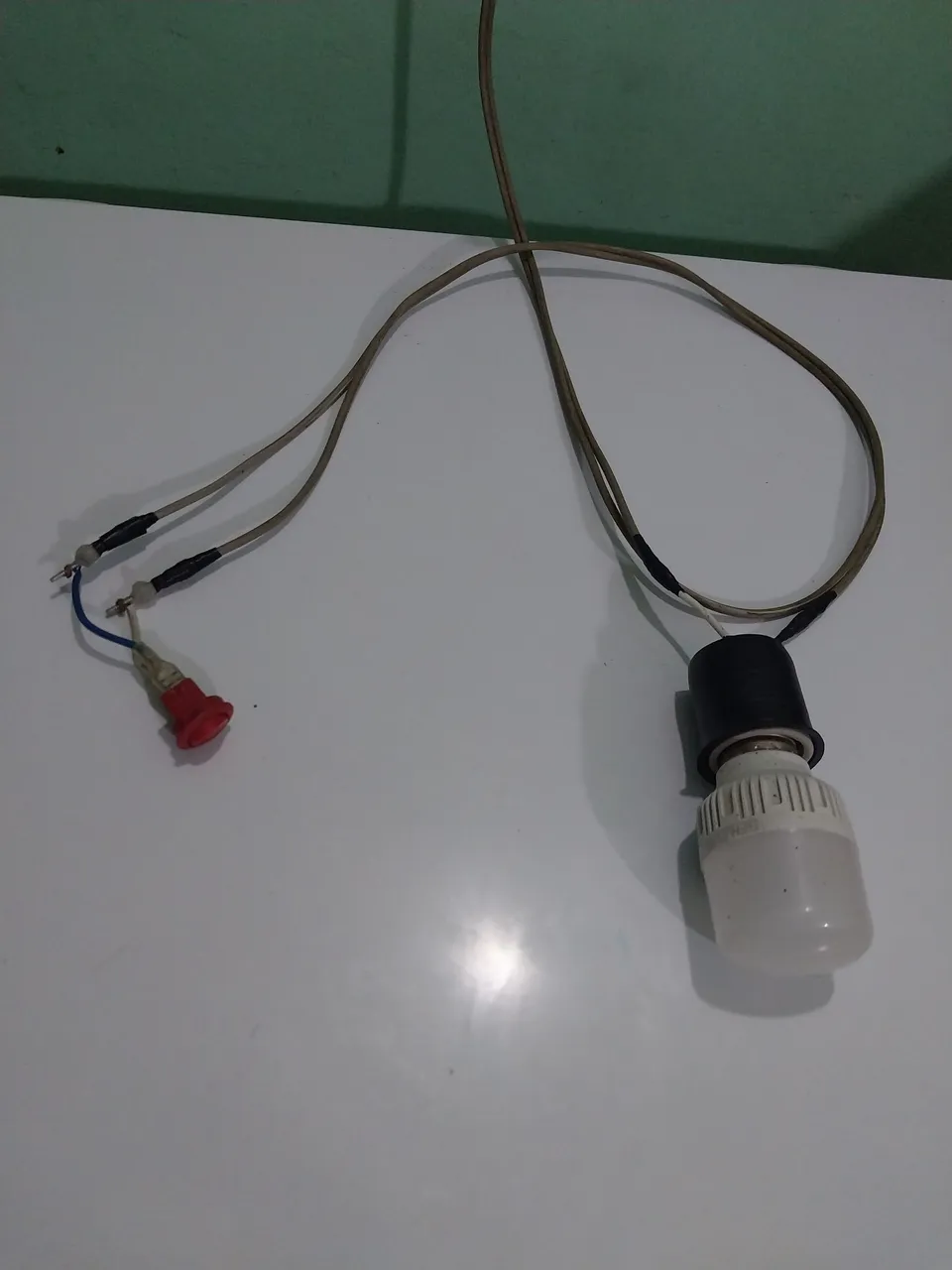
Luego de eso me dirigí hacia el otro extremo del cable y igualmente quite el plástico protector de ambas puntas quedando así el cobre descubierto, pero para que se hiciera más práctico decidí unir mi cobre a unos pequeños tornillos los cuales me iban a facilitar el contacto que iba a necesitar más adelante, una vez que fije bien el cobre a los tornillos decidí echarle un poco de silicón de manera que funcione como un aislante y ayude a mantenerlo de manera firme, también pueden utilizar estaño de manera que el contacto quede mejor, yo lo iba a hacer pero cuando fui a buscar estaño ya se había acabado jaja, y bueno, luego de eso procedí a poner un poco teipe por debajo del silicón de manera que por allí iba a sujetar ese extremo del cable. Y listo, ya está operativo mi Medidor de Continuidad Casero. Ahora, se estarán preguntando ¿para qué sirve? Y bueno, aqui les enseño varias pruebas que hice.
After that I went to the other end of the cable and also removed the protective plastic from both ends leaving the copper exposed, but to make it more practical I decided to attach my copper to some small screws which would facilitate the contact that I would need later, once I fixed the copper well to the screws I decided to put a little silicone so that it works as an insulator and helps keep it firm, you can also use tin so that the contact is better, I was going to do it but when I went to get the tin it was already gone haha, and well, after that I proceeded to put some tape under the silicone so that there I would hold that end of the cable. And that's it, my Homemade Continuity Meter is now operational. Now, you may be wondering what it's for? Well, here I show you several tests that I did.
Luego de eso procedí a probar mi probador de continuidad casero. Tomé mi enchufe, lo conecté al tomacorriente y después me dirigí al otro extremo del cable a juntar las dos puntas, y lo que pasó fue que el bombillo se iluminó, lo cual quiere decir que el probador quedó excelente.
Ahora, ¿para qué se puede utilizar? Su nombre ya dice bastante, es un Medidor de Continuidad Casero, Su función es muy simple. Él nos va a verificar si los componentes que nosotros queremos probar están conduciendo la electricidad correctamente, Osea, lo cual quiere decir que con él podemos probar cables o cualquier componente eléctrico que sea un conductor de electricidad.
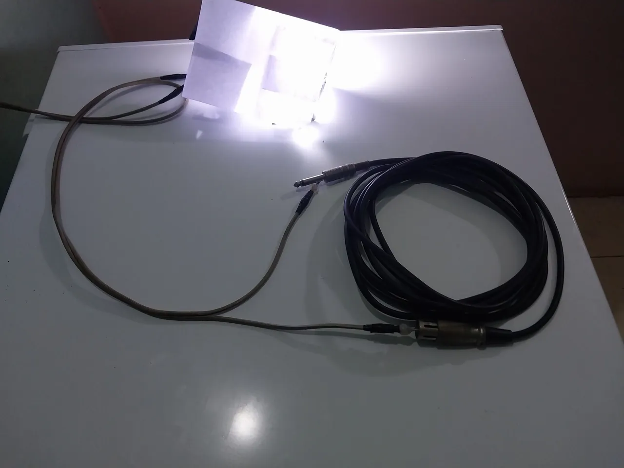
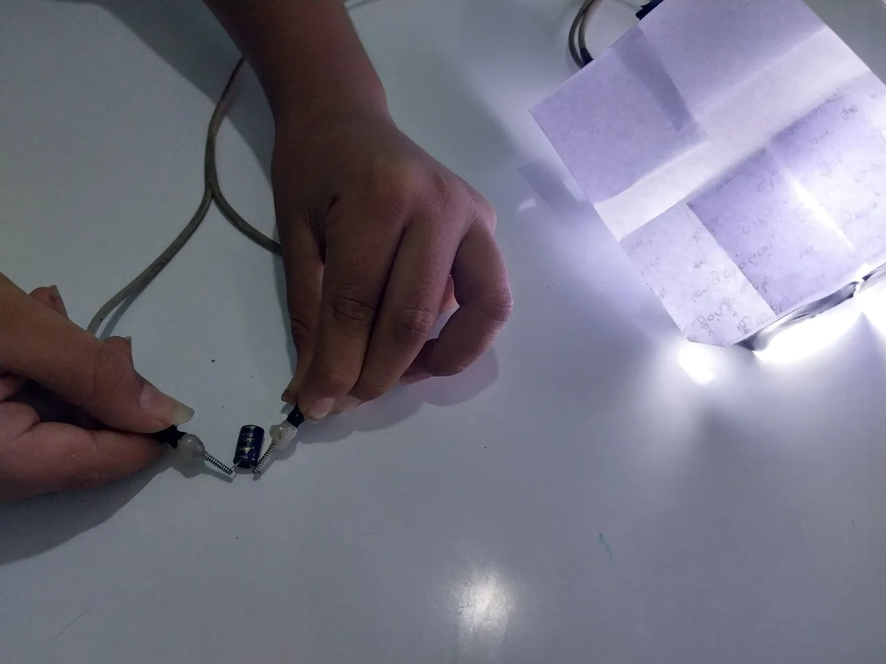
Para mi primera prueba utilicé un cable de sonido. Conecté, fijé una de las puntas a un extremo del cable de sonido y fijé la otra punta al otro extremo, e Inmediatamente el bombillo se iluminó, lo cual quiere decir que la continuidad del cable es correcta y que el cobre no está roto ni tiene ningún problema.
Luego de eso procedí a probar un capacitador. Lo mismo, fijé una punta del cable en una pata del capacitador y la otra punta en la otra pata, ¿y con qué me conseguí? Con que el bombillo también se iluminó, lo cual quiere decir que el capacitador estaba conduciendo la energía correctamente. De no ser así, el bombillo no hubiese encendido.
Y como una última prueba quise probar un encendedor. Procedí a conectar una punta de mi probador a un extremo del encendedor y la otra punta al otro extremo del encendedor. Luego procedí a encender el switch y el bombillo también encendió, lo cual quiere decir que el switch estaba excelente.
Y bueno, infinidades de cosas que podemos probar. De verdad es una herramienta muy útil. La hice porque de verdad que a veces me hace muchísima falta cuando trabajo con mis cosas personales o cuando estoy trabajando con el equipo de la iglesia, siempre tengo que probar, revisar un cable, una resistencia, un capacitador, y para esos momentos esta herramienta me será muy útil. Y estoy muy seguro de que a muchos de ustedes también les va a gustar. Y bueno, ya sin más que decirles, de verdad que espero que disfruten de mi trabajo y que sea de gran utilidad para todos ustedes. Bendiciones y hasta la próxima.
After that, I proceeded to test my homemade continuity tester. I took my plug, plugged it into the outlet, and then moved to the other end of the cable to connect the two leads. What happened was that the light bulb lit up, which means the tester was working fine.
Now, what can it be used for? Its name says it all: it's a Homemade Continuity Meter. Its function is very simple. It will verify if the components we want to test are conducting electricity correctly. This means we can use it to test cables or any electrical component that conducts electricity.
For my first test, I used an audio cable. I connected it, attached one of the leads to one end of the audio cable, and attached the other lead to the other end. Immediately, the light bulb lit up, which means the cable's continuity is correct and the copper wire isn't broken or has any other problems.
After that, I proceeded to test a capacitor. Same thing, I attached one end of the wire to one leg of the capacitor and the other end to the other leg, and what did I get? The bulb also lit up, which means the capacitor was conducting power correctly. If it hadn't, the bulb wouldn't have lit.
And as a final test, I wanted to try a lighter. I proceeded to connect one end of my tester to one end of the lighter and the other end to the other end. Then I proceeded to turn on the switch, and the bulb also lit up, which means the switch was working fine.
And well, there are countless things we can test. It really is a very useful tool. I made it because sometimes I really need it when I'm working with my personal things or when I'm working with church equipment. I always have to test, check a wire, a resistor, a capacitor, and for those times this tool will be very useful. And I'm pretty sure many of you will like it too. Well, without further ado, I truly hope you enjoy my work and that it's of great use to all of you. Blessings, and until next time.
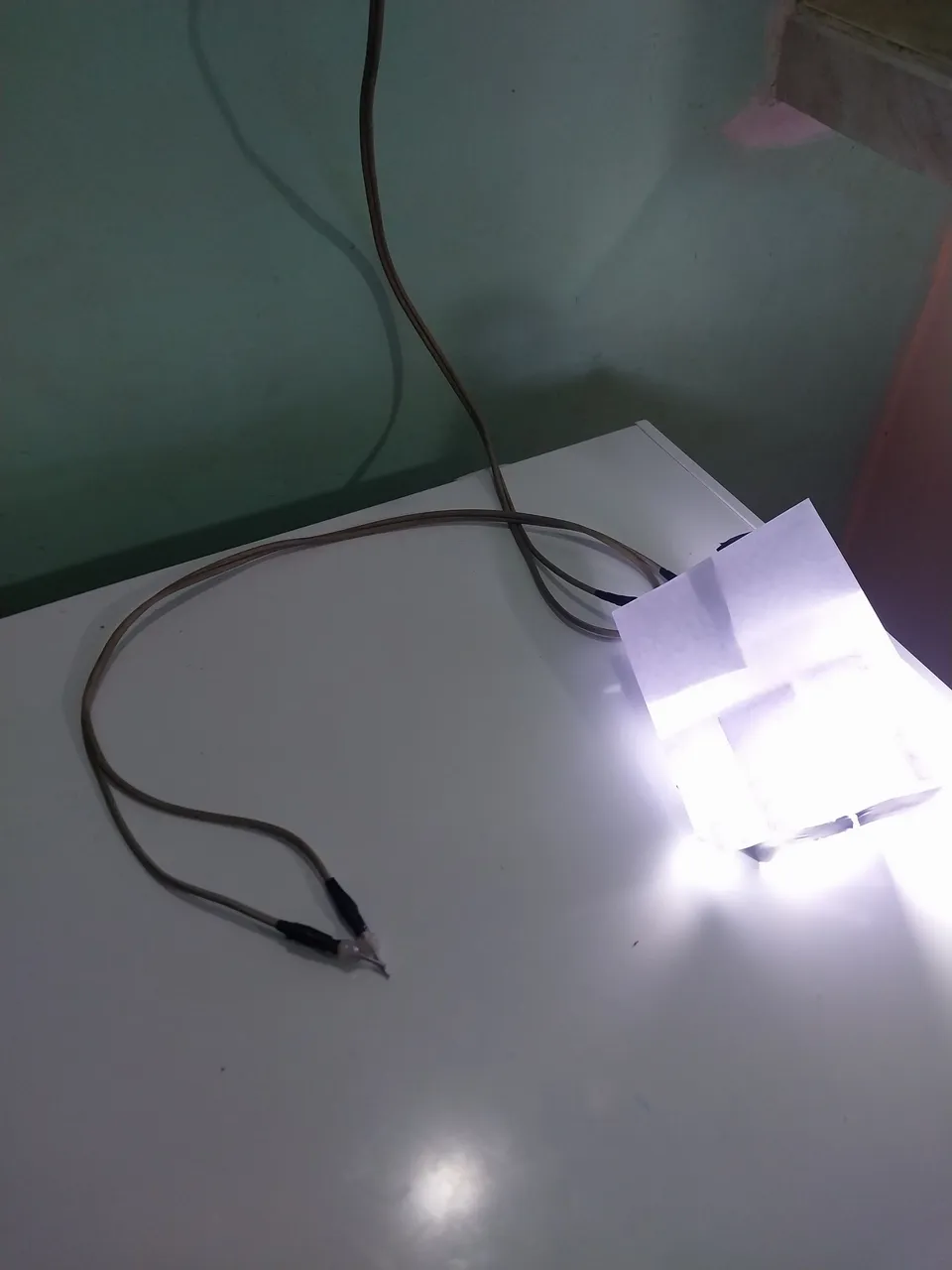
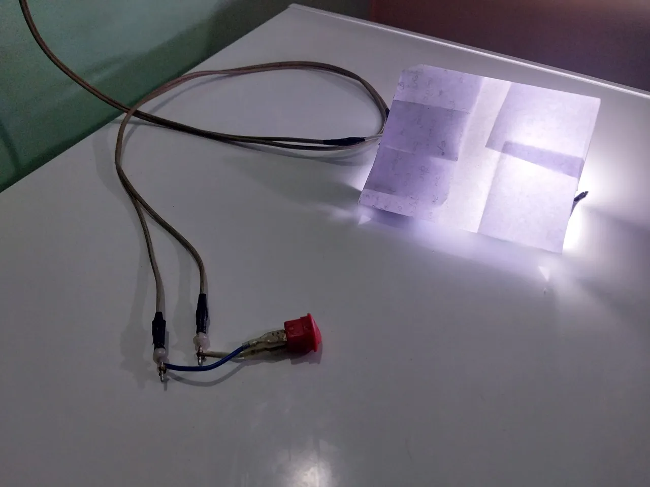
Posdata... Tape el bombillo con un poco de papel porque al tener esa luz directa contra mi cámara me opacada demasiado la fotografía.
P.S. I covered the light bulb with a bit of paper because having that direct light against my camera made the photo too dull.

Translated with https://www.deepl.com/translator