Hola amigos de hive blog como estan hoy? les quiero contar como en mi clase de programacion ya estamos haciendo cosas interesantes y que son 100% funcionales en protoboard🚦🛠️
Todo esto ademas "engancha a los estudiantes" porque es algo llamativo , que en pocas clases funciona y ademas hace pensar a mis alumnos , me encanta jaja.
Hello hive blog friends, how are you today? I want to tell you how in my programming class we are already doing interesting things that are 100% functional in breadboard🚦🛠️
All of this also "hooks the students" because it is something striking, that works in few classes and also makes my students think, I love it haha.
¿Qué necesitamos?
Arduino Uno: El cerebro del proyecto, que controlará las luces del semáforo.
Protoboard: Para montar todo el circuito sin necesidad de soldar.
LEDs de colores (Rojo, Amarillo y Verde): Para simular las luces del semáforo.
Resistencias: Para proteger los LEDs y asegurarnos de que no se quemen.
Cables: Para hacer las conexiones entre el Arduino y el protoboard.
Botón (opcional): Para simular un botón de cruce de peatones. (Esto no lo hicimos)
What do we need?
Arduino Uno: The brain of the project, which will control the traffic light lights.
Breadboard: To assemble the entire circuit without the need to solder.
Colored LEDs (Red, Yellow and Green): To simulate traffic light lights.
Resistors: To protect the LEDs and make sure they don't burn out.
Cables: To make the connections between the Arduino and the breadboard.
Button (optional): To simulate a crosswalk button. (We didn't do this)
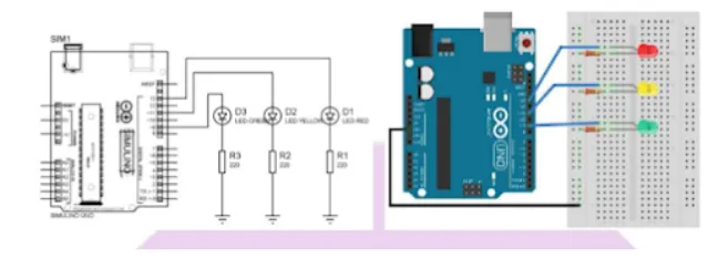
El circuito esquematico o diagrama//The schematic circuit or diagram
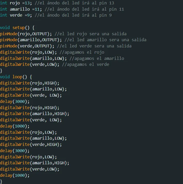
La programacion //The programming
Montaje del circuito en el protoboard
Colocamos los LEDs 💡: Colocamos los LEDs en el protoboard: el rojo en el centro, el amarillo a la derecha y el verde a la izquierda.
Conexión a las resistencias 🔋: Añadimos una resistencia a cada LED para protegerlos y evitar que reciban más corriente de la que pueden manejar.
Conexión a los pines de Arduino 🔌: Los pines digitales de Arduino controlan los LEDs. Los conectamos a los pines 13, 12 y 11 de Arduino para el rojo, amarillo y verde respectivamente.
Alimentación del protoboard ⚡: Usamos los pines de 5V y GND de Arduino para alimentar el protoboard.
Circuit assembly on the breadboard
We place the LEDs 💡: We place the LEDs on the breadboard: the red one in the center, the yellow one on the right and the green one on the left.
Connection to resistors 🔋: We add a resistor to each LED to protect them and prevent them from receiving more current than they can handle.
Connection to Arduino pins 🔌: The Arduino digital pins control the LEDs. We connect them to pins 13, 12 and 11 of the Arduino for red, yellow and green respectively.
Powering the breadboard ⚡: We use the 5V and GND pins of the Arduino to power the breadboard.
Bueno con todas esas instrucciones e indicaciones ustedes mismos pueden hacer funcionar un circuito de similares caracteristicas a este , y tambien pueden desatar su imaginacion y crear cosas super interesantes , un saludo para todos en hive!!
Well, with all those instructions and indications you can make a circuit with similar characteristics to this one work, and you can also unleash your imagination and create super interesting things, greetings to everyone at hive!!