In this post I will display my new vacuum chamber & setup as well as some cool plasma photos! If you are not interested in the science and just want to see some cool pictures, skip to the "First Light" section!
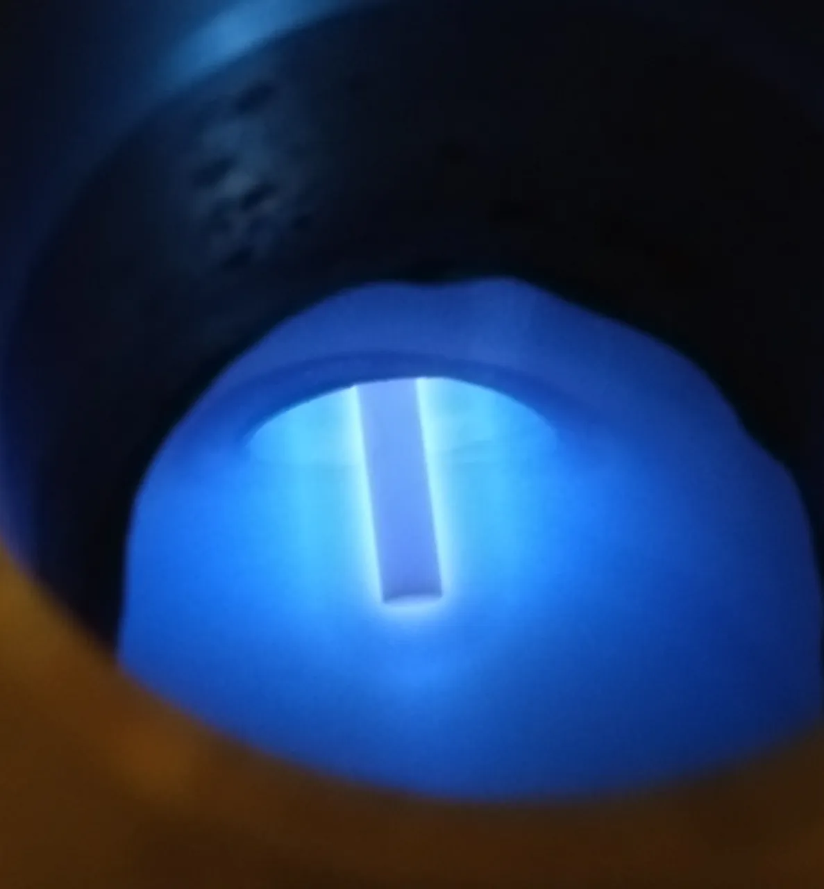
Figure 1. Plasma being formed around an electrode.
Vacuum Chamber
Vacuum chambers are rarely encountered on a day to day basis so I will explain what a vacuum chamber is and how I constructed mine.
A vacuum chamber is the opposite of a pressure vessel. Pressure vessels, such as compressors and soda cans, are meant to keep gas inside them while vacuum chambers are designed to keep the gas out. The reason why a vacuum is needed to do many experiments is exceptionally complicated and deserving of its own article. In short, the less molecules in a confined space, the easier it is to experiment with individual particles. When there are so few molecules that the particle is more likely to collide with a wall or macroscopic object as opposed to a gas molecule, then the flow is called molecular. This allows particles to be modeled as individual units and not as a continuum fluid. This is very helpful for particle physics and many other processes. A good comparison is a game of billiards. It is much easier to get the ball in the corner when there are not a ton of balls in your way! The balls are like the gas molecules in the air and by removing them, some very interesting things can occur! To get back to vacuum chambers, many of them contain complex equipment as well as specialized ports to allow very small amounts of chemicals into the chamber for experiments. The one that I have constructed is simple since it only has electrical inputs for now. I will be adding more ports to expand the abilities of my chamber soon!
My Chamber
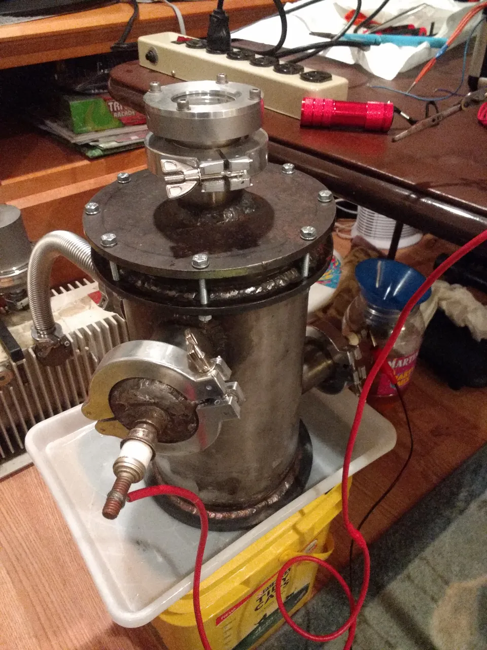
Figure 2. High voltage feed-through on the side and small viewport on the top. Other electrical connection is on the opposite side of the chamber.
The chamber that I constructed is quite simple and besides a TIG welder, requires only common tools to build. Before I purchased my TIG welder, I attempted to do much of the welding with a DC flux core wire welder. I was only able to get good leak free welds on two of the small flanges but I had to redo almost all of the other welds with TIG. Going over flux core welds with TIG them makes it look extremely bad and I am no expert at welding which does not help. The TIG weld at the bottom of the chamber is one that I completed with TIG only and you can see the difference. If you decide to build your own vacuum chamber, I would highly suggest having someone else weld it, or use either TIG or MIG to weld it. Avoid anything with flux, including stick, since the flux will be prone to induce leaks and outgassing in the chamber.
As for the actual construction, the cylindrical portion of the chamber is made of 6" diameter schedule 40 304 stainless steel pipe. The bottom welded plate is simply made of mild steel and I completed the welds between them with ER309L filler rod. Since I wanted the inside of the chamber to be accessible, I made the top a bolt on flange to allow internal access. The attached bolt feed through flange was made by cutting out a large hole in a round piece of mild steel and welding it to the chamber body. The top piece simply has bolt holes drilled into it to allow for a tight clamping. In addition, a hole was cut for a KF 50 flange which was then welded in place. This is where the viewport is connected. I made the very large holes by drilling around a ring with a 1/4" bit a large number of times then finishing it off with an angle grinder. For the many KF vacuum flanges on the chamber, I simply purchased hole saws and very carefully cut holes in the chamber with my small drill press(10") and lots of cutting oil.
Vacuum Pump
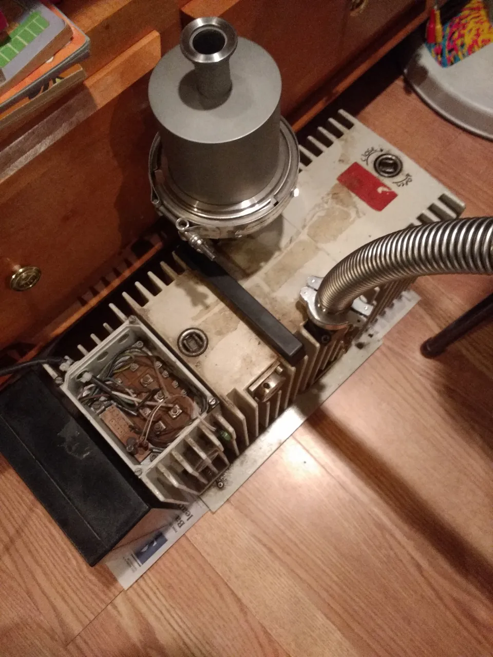
Figure 3. Pump model is a Pfieffer Balzers DUO 016B dual vane rotary vacuum pump. The large silver can is an oil mist filter on the exhaust
The vacuum pump that I am using for my experiments is a large dual rotary vane vacuum pump. The pump works by making a constantly increasing volume on the vacuum side which sucks air in. It then expels this air outward on the exhaust. I purchased this pump used off of Ebay and had to repair a few internal components to get it operational. I took a picture of the pumping mechanism which can be viewed below.
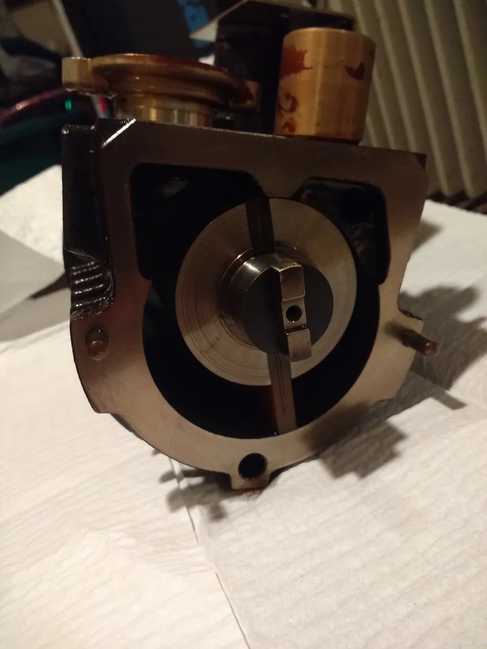
Figure 4. The pumping mechanism rotates counterclockwise and the little plastic pieces(vanes) move such that they are always in contact with the chamber outer surface. This creates a vacuum on the inlet side.
High Voltage Supply
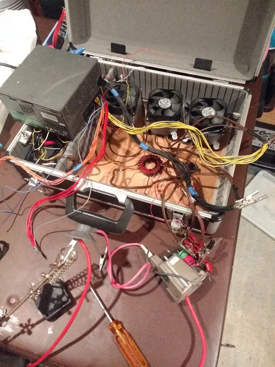
This is the same high voltage power supply that I used in my other plasma project with a few things modified. The voltage output is only around 10kV compared to around 20kV in my other post. The voltage is fed in on the side of the chambers and ionizes stray gas molecules causing the plasma. The power supply is a bit of a mess since I had to adjust some components.
In my later images I upped the voltage to around 16kV but did not take a picture of this setup since it is essentially the same as above with one additional transformer(and more messy wires).
FIRST LIGHT
This image was taken the first time I plugged the high voltage in.
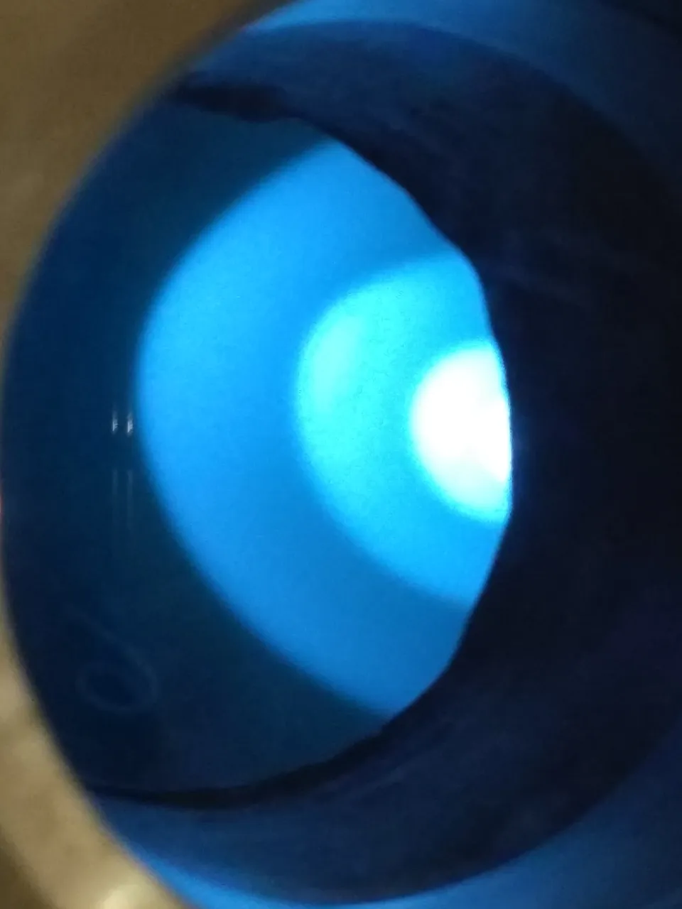
Figure 5. Electron 'shockwaves' are clearly visible near the positive electrode(out of view to the left)
What is happening in the above image is that electrons are gaining and loosing energy in distinct layers such that they cause different densities of ionization. These electrons are emitted from a negative electrode out of view. As the electrons are expelled from the negative electric field around the electrode, they ionize the few gas molecules remaining in the chamber. This creates a constant dull glow which is out of view in this image. Eventually, the electrons loose enough energy that they no longer can ionize gas molecules. This occurs in the dark area to the left of plasma layers. Once the electrons begin closing in on the positive electrode, they accelerate again(think of falling rock picking up speed). Once they hit a certain threshold of kinetic energy, they begin to ionize gas molecules again which is why you get the outermost layer. However, after they collide with the gas molecules they are slowed down and have to regain speed to initiate ionization again. This is why you see multiple layers and not one continuous spectrum. '
My camera had a hard time picking up the plasma due to the large light contrast but the layers are actually 3 dimensional and somewhat look like a sideways mountain with the 'peak' pointed towards the other electrode. I have ordered a much larger viewport so hopefully I will be able to capture some good images of it soon.
Additional Testing and Plasma Confinement
Within the pictures, you can see many things, including the difference between molecular flow and viscous flow. In the images where there are no "shell" lines (electron shocks), that is essentially molecular flow. In the images where the plasma is very diffuse and there are no electron shocks, the gas is behaving much closer to molecular inviscid flow conditions.
I have a Pirani vacuum gauge that I have not set up yet, so I do not know the actual pressure. Once the actual pressure is known, I can confirm whether or not the flow is molecular. My reasoning behind the above statements is that in the images with electron shocks and the confinement, you can see a plume of plasma escaping. This plume bends outward from its origin, which is an indication that viscous effects are still present(Figure 10 & 11). Additionally, the electron shocks indicate that the electrons are loosing their energy relatively quickly via gas molecule collisions. In Figure 13 & 14, you can see that instead of a bending plume, the plasma is more column like and appears to shoot out like a laser. This is a good indication that viscous effects are minimal or nonexistent, and that the flow transitioning to molecular. Electron shocks are still present in these images so it is likely that viscous effects are still present but very small. In Figure 12, you can also see a continuum of diffuse plasma throughout the entire chamber, this indicates that at least some electrons are keeping their energy far away and not dropping below ionization energies. Since the plasma is so diffuse, it is highly likely that this has completely transitioned to molecular flow.
All images beyond Figure 6 (also including Figure 1) are being operated at a higher voltage. I wired two transformers such that I was getting roughly 16kV (judging by arc distance) which makes a much more visible plasma.
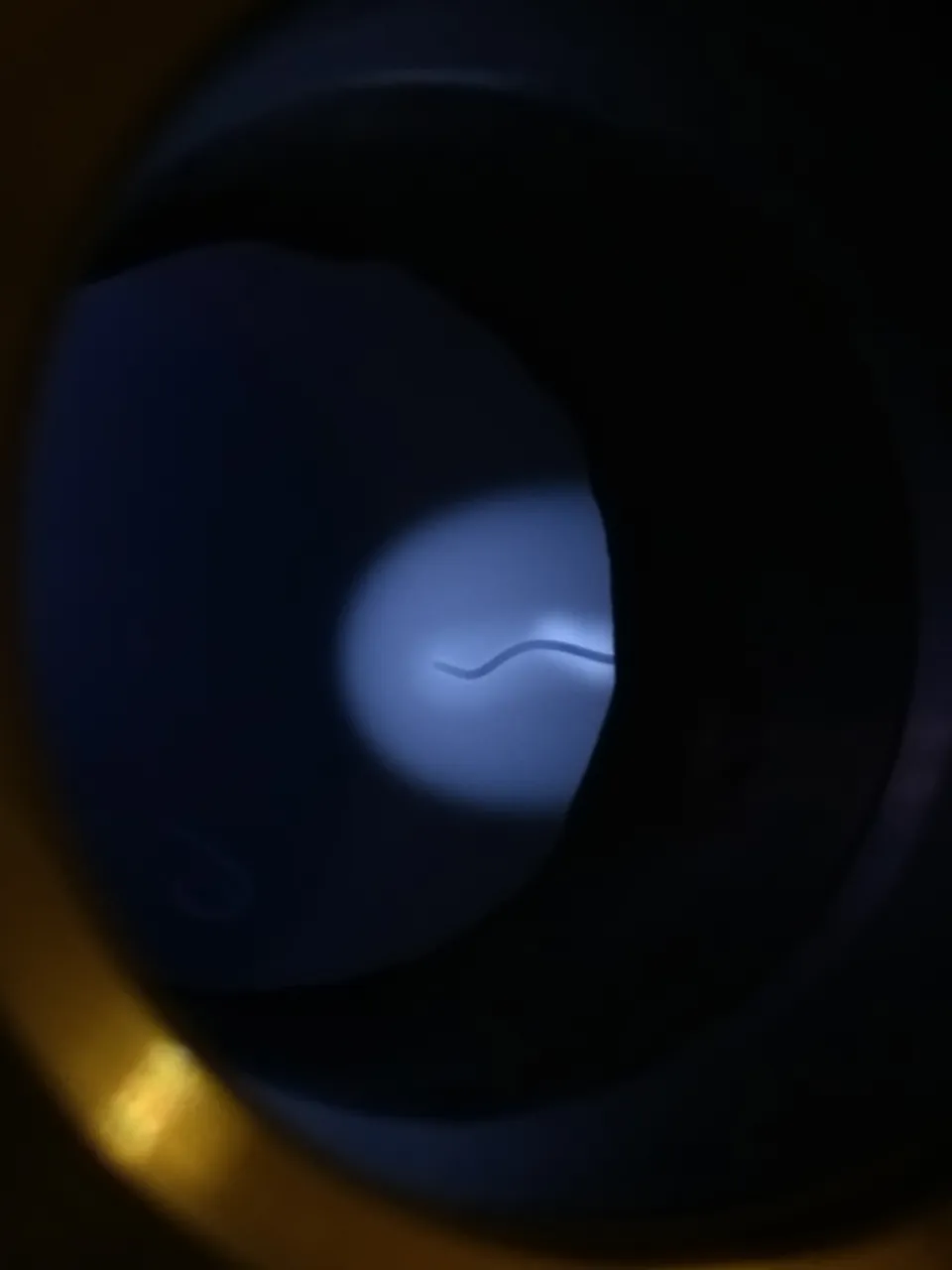
Figure 6. Lower voltage plasma weakly ionizing gas around a wire
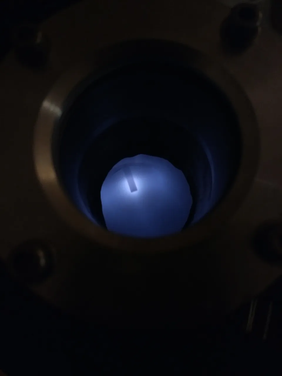
Figure 7. Plasma density is pushed closer to the tip of the electrode as pressure drops.
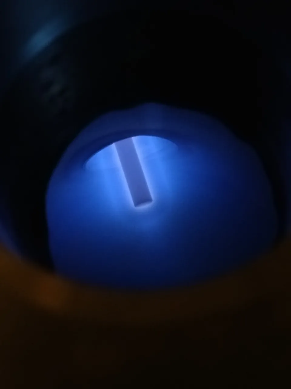
Figure 8. Beautiful blue plasma around a large copper electrode.
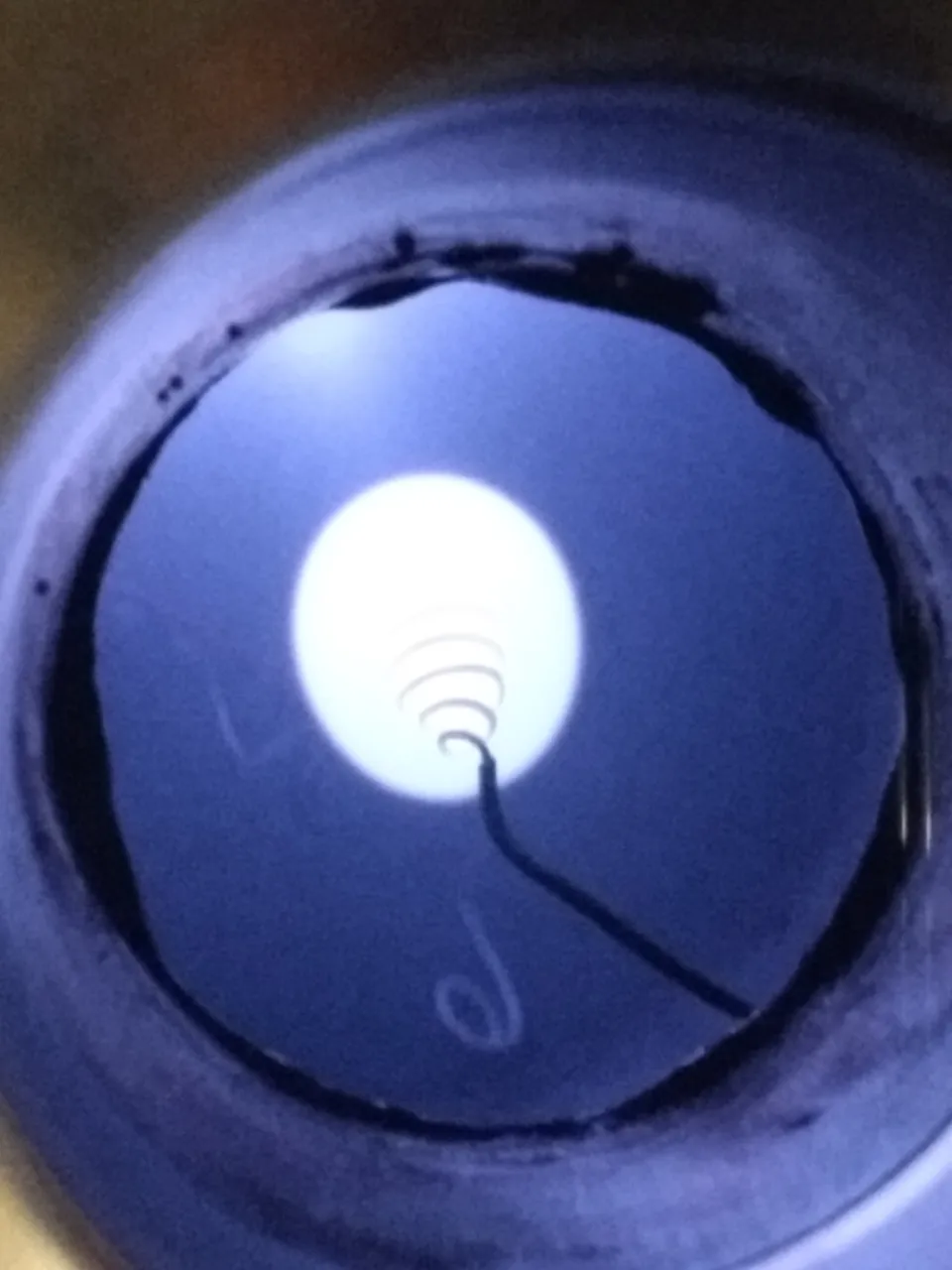
Figure 9. The chamber was not pumped as low as in the other images. This is why the plasma is so dense
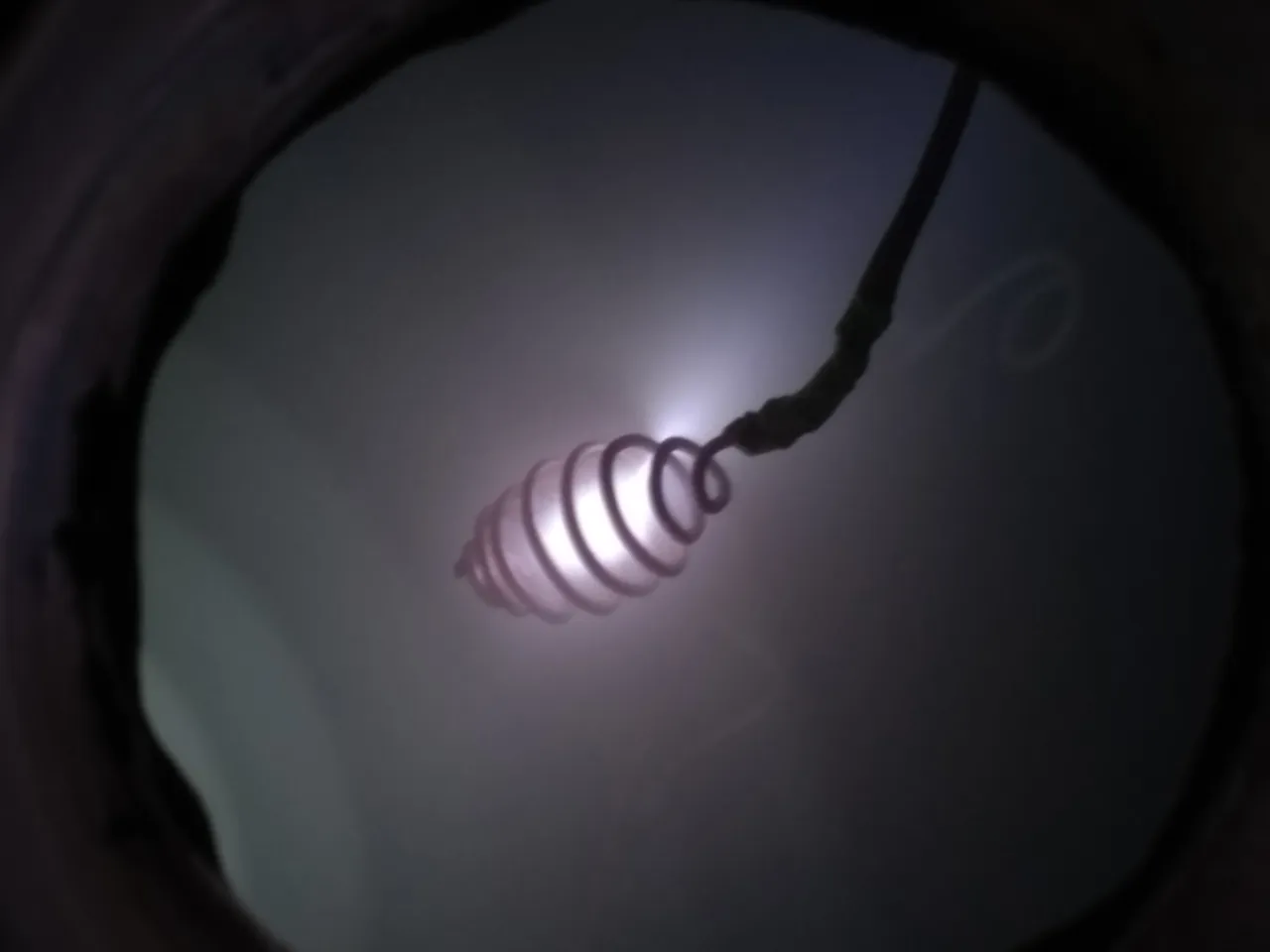
Figure 10. Diverging plasma plume and well defined electron shocks indicate viscous flow conditions
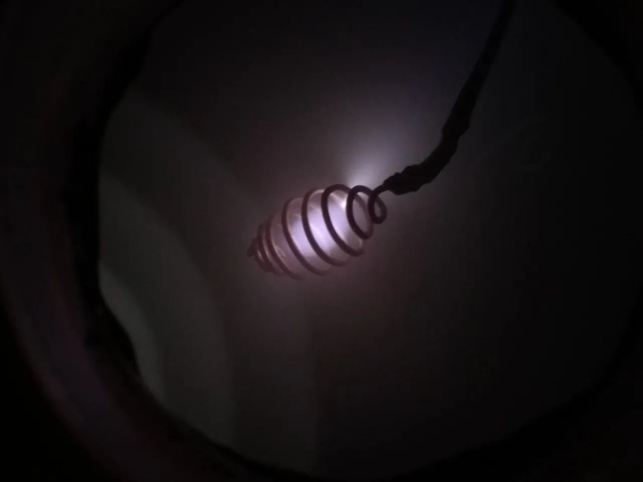
Figure 11. Diverging plasma plume escaping from confinement. Viscous effects are present
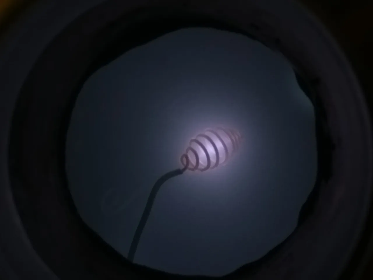
Figure 12. No indications of viscous effects. Likely molecular flow conditions
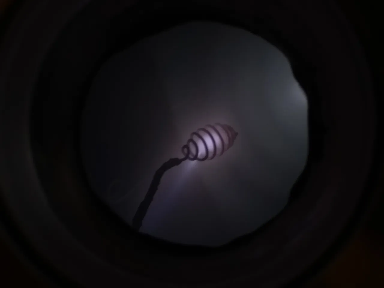
Figure 13. Electric potential is strong enough to negate most of the viscous effects, hence the beam of plasma. Electron shocks are still present so it is not entirely molecular.
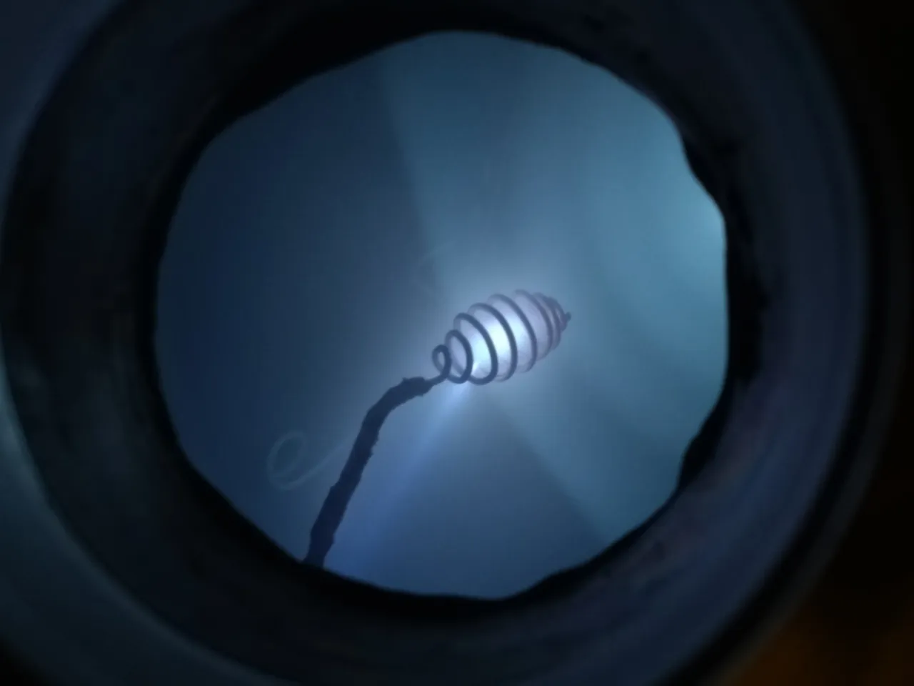
Figure 14. Plasma jet clearly visible along with very distant electron shocks. Flow is approaching molecular conditions
I hope you enjoyed this article as much as I enjoyed writing it! If you have any thoughts, complaints, suggestions, or questions, please leave a comment below! I greatly appreciate feedback on these articles so I can improve my writing for next time!
Also, if anyone has any suggestions for things to try in a vacuum, let me know! I have a few ideas of some things I want to do which I will save for later.
Thanks for reading! Hellfire Labs