[ESP]
Hola, hermosa comunidad de Hive! 👋
Hoy continuamos nuestra serie sobre amplificadores operacionales con la configuración restador. 🌟 Este tipo de amplificador es esencial para muchas aplicaciones en electrónica, especialmente cuando necesitamos calcular la diferencia entre dos voltajes. 🔋
Amplificador Operacional en Configuración Restador
¿Qué es un Amplificador Restador? 🤔
Un amplificador restador produce una salida proporcional a la diferencia de dos voltajes de entrada. Es útil en aplicaciones donde es necesario comparar señales, eliminar interferencias comunes o realizar mediciones precisas. 📊
Circuito y Análisis 🔍
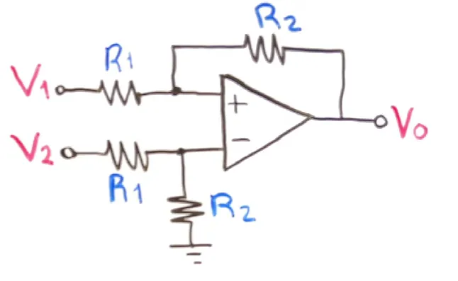
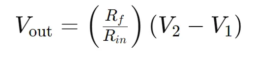
El circuito de un amplificador restador se compone de un amplificador operacional con resistencias específicas conectadas a las entradas inversora y no inversora. La fórmula general para la salida del amplificador restador es:
Donde:
- 𝑉1 y 𝑉2 son los voltajes de entrada.
- 𝑅𝑓es la resistencia de retroalimentación.
- 𝑅𝑖𝑛 es la resistencia de entrada.
Paso a Paso del Análisis 🛠️
- Configuración del Circuito: Conecta las resistencias y las entradas al amplificador operacional.
- Aplicación de la Ley de Kirchhoff: Aplica la ley de Kirchhoff para las corrientes y voltajes en el circuito para derivar la ecuación de salida.
- Simplificación: Simplifica la ecuación para encontrar la relación entre la salida y las entradas.
- Resultado Final: La salida es proporcional a la diferencia entre las dos entradas, escalada por el facto

Usos del Amplificador Restador 🛠️
- Eliminación de Señales Comunes: En sistemas de medición, puede eliminar señales de ruido comunes a ambos canales.
- Comparación de Señales: Comparar y procesar señales en sistemas de control.
- Medición de Variaciones Pequeñas: Utilizado en instrumentación para medir variaciones pequeñas en sensores.
Ejemplo Práctico 📐
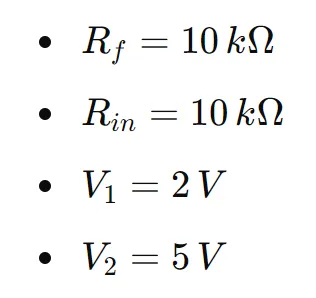
Supongamos que tenemos un amplificador restador con las siguientes características:
La salida sería:
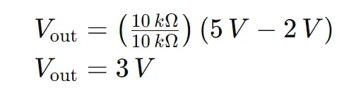
Esto demuestra cómo el amplificador restador puede utilizarse para calcular diferencias precisas entre dos voltajes. 📉
Conclusión
📢 ¡Gracias por leer! Mantente conectado para más contenido educativo 📚
Espero que este post te haya sido útil. Si fue así, no olvides dejar un comentario y compartir tus pensamientos o preguntas. 📝
🔔 No te pierdas mis próximas publicaciones donde seguiremos explorando el fascinante mundo de la electrónica y los circuitos. Cada semana, voy a traer nuevos temas, ejemplos prácticos y recursos para que sigas aprendiendo y mejorando tus habilidades. 🌐
🤝 Sígueme en mis redes sociales, donde podrás conectarte con otros entusiastas de la electrónica, hacer preguntas y recibir ayuda en tiempo real. ¡Estamos aquí para ayudarte! 💬
📷 Comparte tus proyectos: Si has aplicado estos conocimientos en tus propios proyectos, ¡nos encantaría verlos! Comparte tus avances y aprende de otros en nuestra comunidad. 🛠️
🌟 Mantente en contacto: Sígueme en mis redes sociales para actualizaciones, contenido exclusivo y más consejos sobre electrónica y circuitos. Tu participación y apoyo son lo que hace que esta comunidad crezca y se enriquezca. 📈
¡Nos estamos leyendo! Hasta entonces, sigue explorando, aprendiendo y compartiendo. ¡Juntos, hacemos la electrónica más accesible y emocionante para todos! 🚀✨
[ENG]
Hello, beautiful Hive community! 👋
Today we continue our series on operational amplifiers with the subtractor configuration. 🌟 This type of amplifier is essential for many electronic applications, especially when we need to calculate the difference between two voltages. 🔋
Operational Amplifier in Subtractor Configuration
What is a Subtraction Amplifier? 🤔
A subtractor amplifier produces an output proportional to the difference of two input voltages. It is useful in applications where it is necessary to compare signals, eliminate common interferences or make precise measurements. 📊
Circuit and Analysis 🔍
The circuit of a subtracting amplifier consists of an operational amplifier with specific resistors connected to the inverting and non-inverting inputs. The general formula for the output of the subtractor amplifier is:
Where:
- 𝑉1 and 𝑉2 are the input voltages.
- 𝑅𝑓is the feedback resistance.
- 𝑅𝑖𝑛 is the input resistance.
Step by Step Analysis 🛠️
- Circuit Configuration: Connect the resistors and inputs to the operational amplifier.
- Application of Kirchhoff's Law: Apply Kirchhoff's law for the currents and voltages in the circuit to derive the output equation.
- Simplification: Simplify the equation to find the relationship between the output and the inputs.
- Final Result: The output is proportional to the difference between the two inputs, scaled by the facto
Uses of the Subtractor Amplifier 🛠️
- Elimination of Common Signals: In measurement systems, it can eliminate noise signals common to both channels.
- Signal Comparison: Compare and process signals in control systems.
- Measurement of Small Variations: Used in instrumentation to measure small variations in sensors.
Practical Example 📐
Suppose we have a subtraction amplifier with the following characteristics:
The output would be:
This demonstrates how the subtractor amplifier can be used to calculate precise differences between two voltages. 📉
Conclusion
📢 Thanks for reading! Stay tuned for more educational content 📚
I hope this post has been useful to you. If so, don't forget to leave a comment and share your thoughts or questions. 📝
🔔 Don't miss my next posts where we will continue exploring the fascinating world of electronics and circuits. Each week, I'll bring new topics, practical examples, and resources to keep you learning and improving your skills. 🌐
🤝 Follow me on my social networks, where you can connect with other electronics enthusiasts, ask questions and receive help in real time. We are here to help you! 💬
📷 Share your projects: If you have applied this knowledge in your own projects, we would love to see them! Share your progress and learn from others in our community. 🛠️
🌟 Stay in touch: Follow me on my social networks for updates, exclusive content and more tips on electronics and circuits. Your participation and support are what make this community grow and enrich. 📈
We are reading each other! Until then, keep exploring, learning and sharing. Together, we make electronics more accessible and exciting for everyone! 🚀✨