What Will I Learn?
- You will learn how to draw a serrated sphere
- You will learn SolidWorks tools used in sphere drawing
- You will learn some features of the SolidWork interface
- General content of the program
Requirements
- SolidWorks program
- Know SolidWorks interface at a simple level
- Basic knowledge of 3d geometry
Difficulty
- Basic
Firstly ; What Is SolidWorks and What Does It Do
Solidworks is a solid modeling and editing program for the design of these participations. To make technical drawings, to measure them and to allow them to participate in these dimensioned drawings.
Allows many components to be assembled and to see both their formal and functional adequacy. We can deliver all of these drawings in different paper sizes (A4, A3, A2 etc.) which can be transferred to the technical drawing file.
GENERAL CONTENT OF THE PROGRAM
- Profile drawings
- Actions to be applied to Profiles
- Image adjustments
- Sketch based applications
- Solid modeling
- Changing the coordinates of the solid model with translation
- Sheet metal forming
- Surface creation operations
- Surface-based solid formation
- Application of the mold required for the manufacture of parts
- Assembly of parts
- Constraining constraints
- Mechanisms of movement
- Motion blockers in mechanics
- Dependent movements in mechanics
- Tool call with toolbox to assemblies
- Adding fast parts with Smart Mate
- Removing technical drawings
- Creating an image
- Dimension
- Entering the assembly numbers
- Shape and dimensional tolerances
- Linear stress analysis of a simple part with Cosmos Works
- Thermal analysis of a simple part with Cosmos Works
- Buckling analysis
- Optimization tests
- Testing a designed part under all kinds of boundary conditions
- Defining the connections of the simple mechanism with the aid of Cosmos Motion
- Friction attachment
- Finding impulse momentum values that should occur as a collision result
- Simulation of mechanics
Make Your Own Serrated Sphere
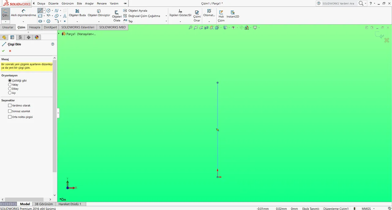
After we open the program we draw a vertical line starting from the origin with our line command. If you want, you can measure from the upper left measurement command.
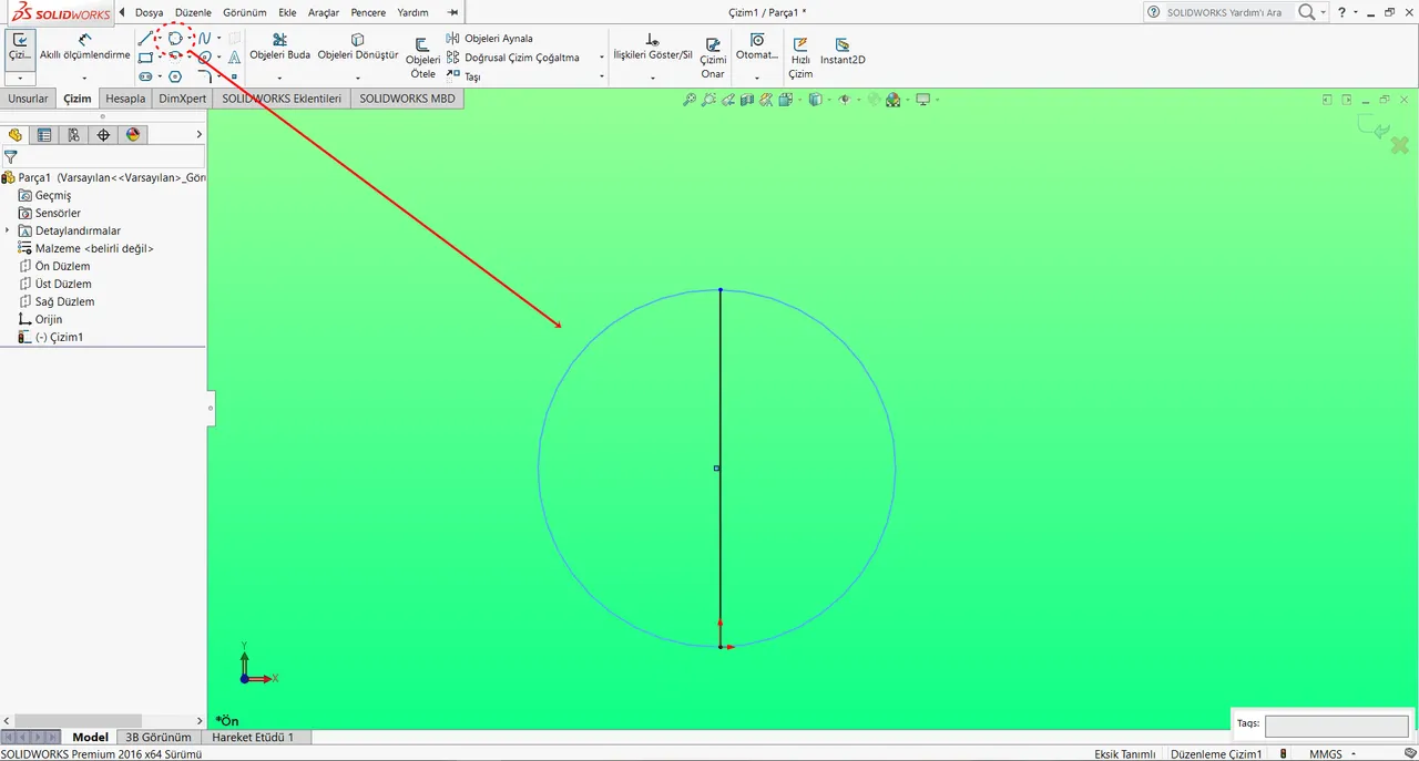
After drawing the line, we draw a circle with 3 points from where I pointed in the picture. The first of these 3 points is the origin, the second is the end point of our line, and the third point is any point that does not disturb the ratio setting.
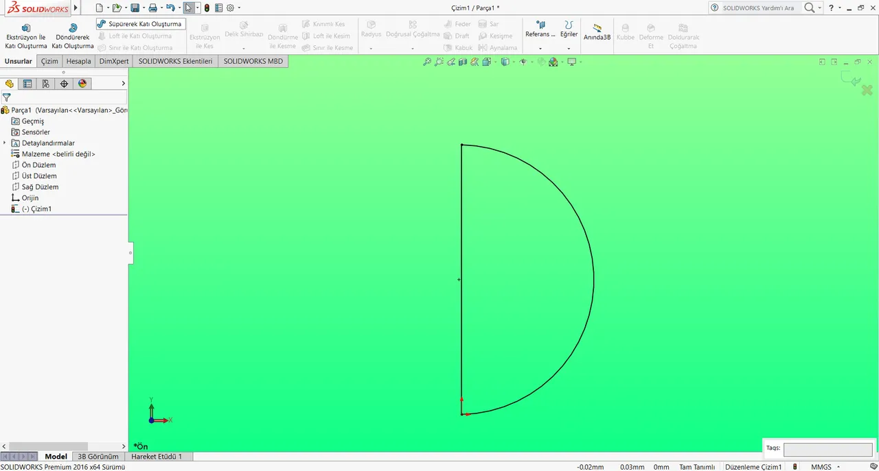
After we do this, we cut the left side of the circle. The figure below appears
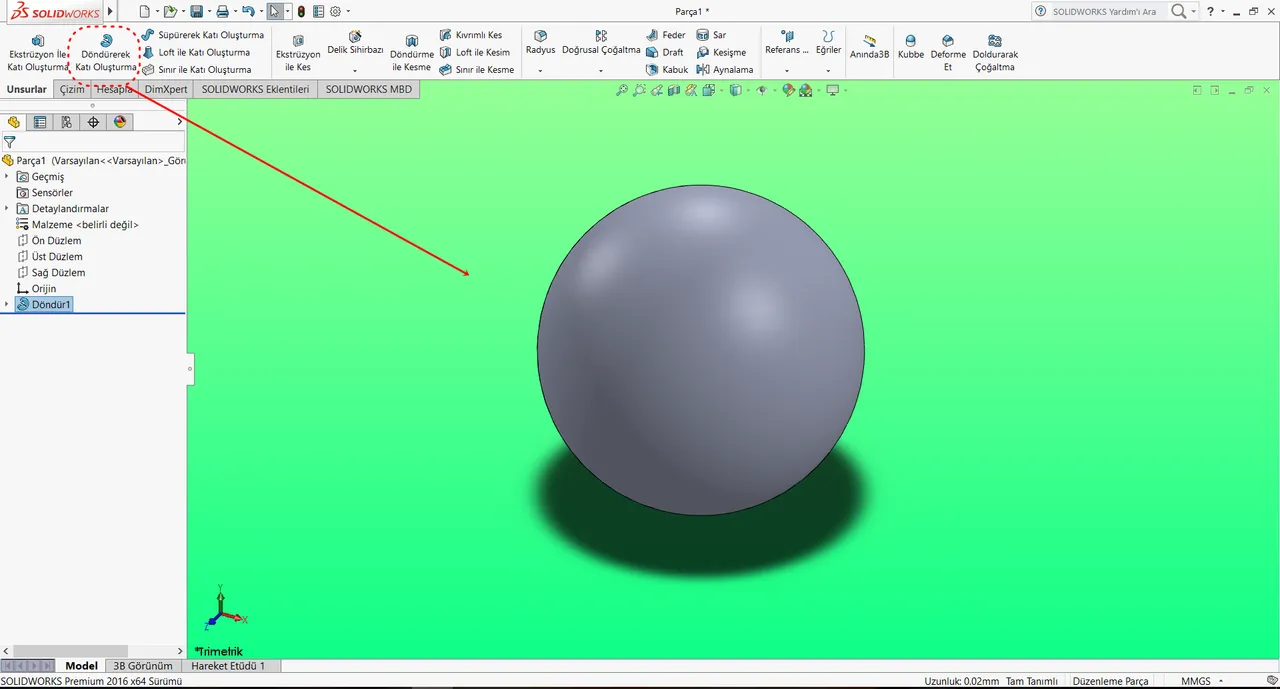
After we do this, we create the sphere using the spinning solid command on the top left. During the process, we choose the line that we draw as the axis of rotation.
Then we open the drawing in the front plane and draw 8 circles as shown. When drawing these circles, let's pay attention to the fact that it is half of the big circle.
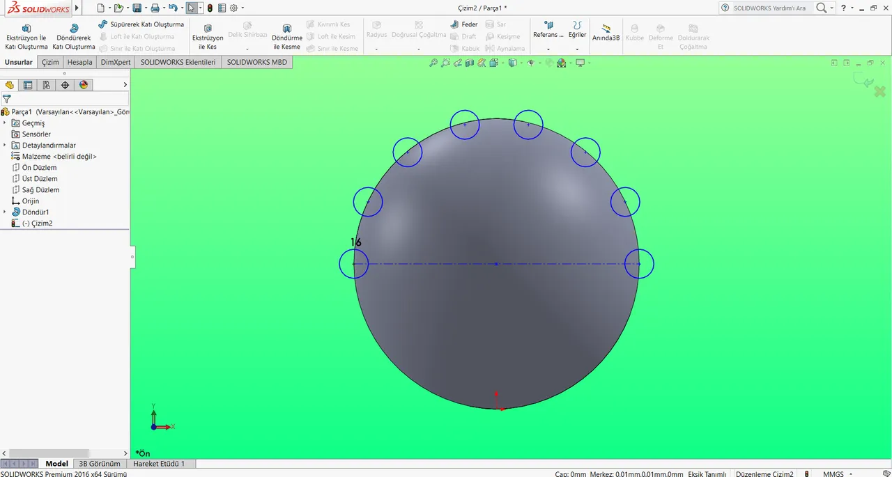
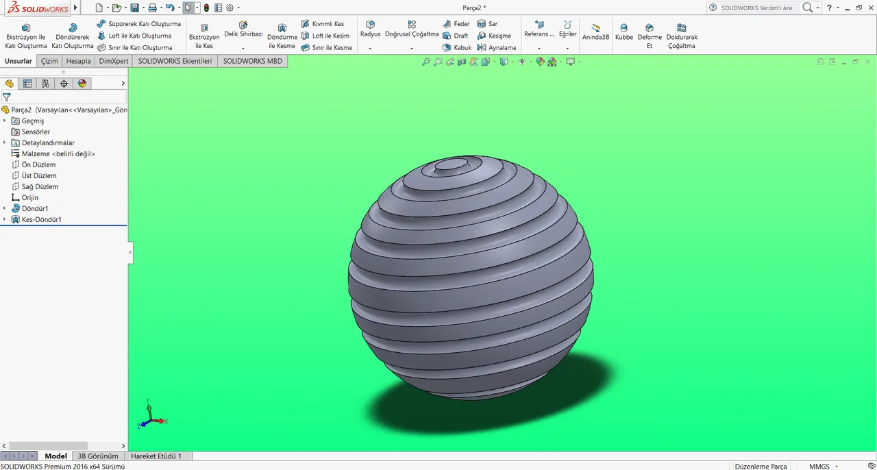
Finally, cut the small circles of large circle using the "rotate by cut" command in the upper left. Here, we may need to create an axis. If necessary, you can add lines in the top left drawing command. When we do all these perfectly, we get this shape.
Hopefully you have learned
Posted on Utopian.io - Rewarding Open Source Contributors