Repository
https://github.com/SUPLA/arduino
Technological progress aims to make life easier for people. We invented cars to make us able to travel more comfortable, faster and further. We invented light bulb to make us able to function during a night. However, for a long time, there was no revolutionary inventions affecting homes which served mostly as a shelter. Finally, in 1982, IoT (Internet of Things) technology has appeared and quickly became disruptive. It allows to connect devices in a network, where they can communicate and share information with each other.
Nowadays, there are plenty of platforms using IoT, through which you can make your home intelligent and control it using your smartphone or voice. Unfortunately, these platforms are usually complex, expensive and closed. As there is stated on the Supla page:
SUPLA is simple, open and free of charge. It gives an opportunity to build elements based on RaspberryPI, Arduino or ESP8266 platforms and then join them either through LAN or WiFi. Through SUPLA you can, among others, control the lighting, switch on and off household appliances and media, open and shut gates and doors, or control room temperature.
Supla is a Polish project and has a rich community, which willingly develops new solutions and features. However, there is a lack of knowledge about Supla in English, which causes less interest in this project worldwide. I want to change that situation by a series of tutorials, explaining major features of Supla.
What Will I Learn?
- You will learn how to connect Arduino to the internet
- You will learn how to use SuplaDevice library
- You will learn how to configure Supla on Arduino
Requirements
- Smartphone
- Arduino Mega
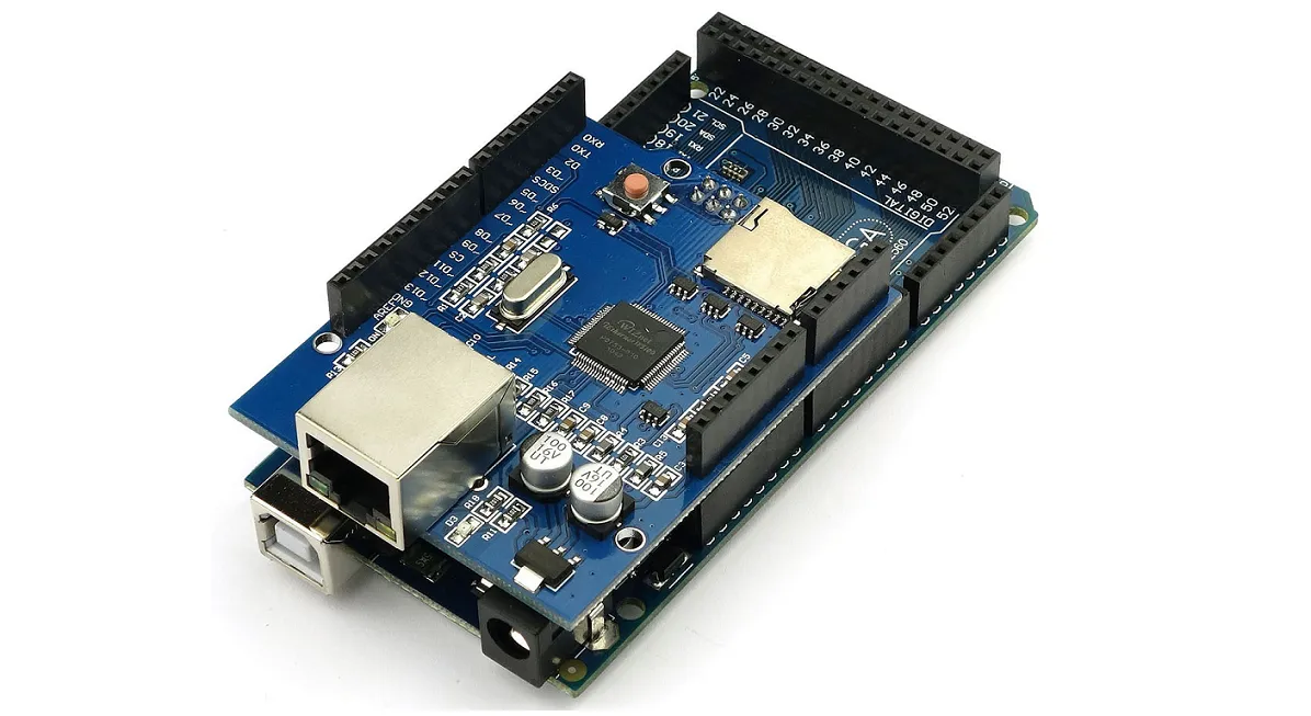
- Ethernet Shield or ENC28J60
- NPN Transistor (e.g. BC547B)
- Resistor 10K
- Relay module
- 5V supply
- Arduino IDE
Difficulty
Intermediate
Tutorial Contents
- First we need to connect Arduino to the internet. You can do it either using Ethernet Shield or ENC28J60.
In case of Ethernet Shield, simply attach it to the Arduino:
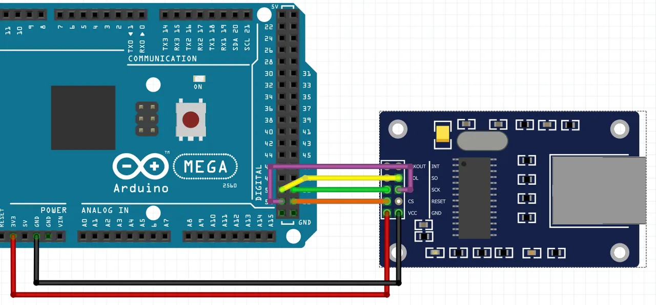
In case of ENC28J60 you need to connect following pins using wires:
| ENC28J60 | Arduino Mega |
|---|---|
| VCC | 3,3V |
| GND | GND |
| SCK | Pin 52 |
| SO | Pin 50 |
| SI | Pin 51 |
| CS | Pin 53 |
- Connect a relay with the Arduino pin 44 (this particular pin is very important) using the scheme below. To avoid situation when too high current flows through Arduino board (this may affect the correct work of the device) we have to control relay using NPN transistor and supply it from the external source. We also have to limit the current reaching the transistor base. For this purpose, we use a 10K resistor before it.

Arduino applies voltage between the base (2) and the emitter (3), which turns the transistor on. It allows a current to flow from the collector (1) to the emitter (3) and triggers the relay.
Important: Arduino has to be powered from the same source as relay.
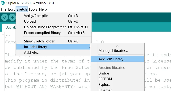
- Download Supla library for Arduino, which allows you to integrate your device with Supla ecosystem. Open Arduino IDE, go to Sketch -> Include Library -> Add .ZIP Library... and select downloaded .ZIP file. Important: if you are using ENC28J60, you need to install additionally UIPEthernet library.
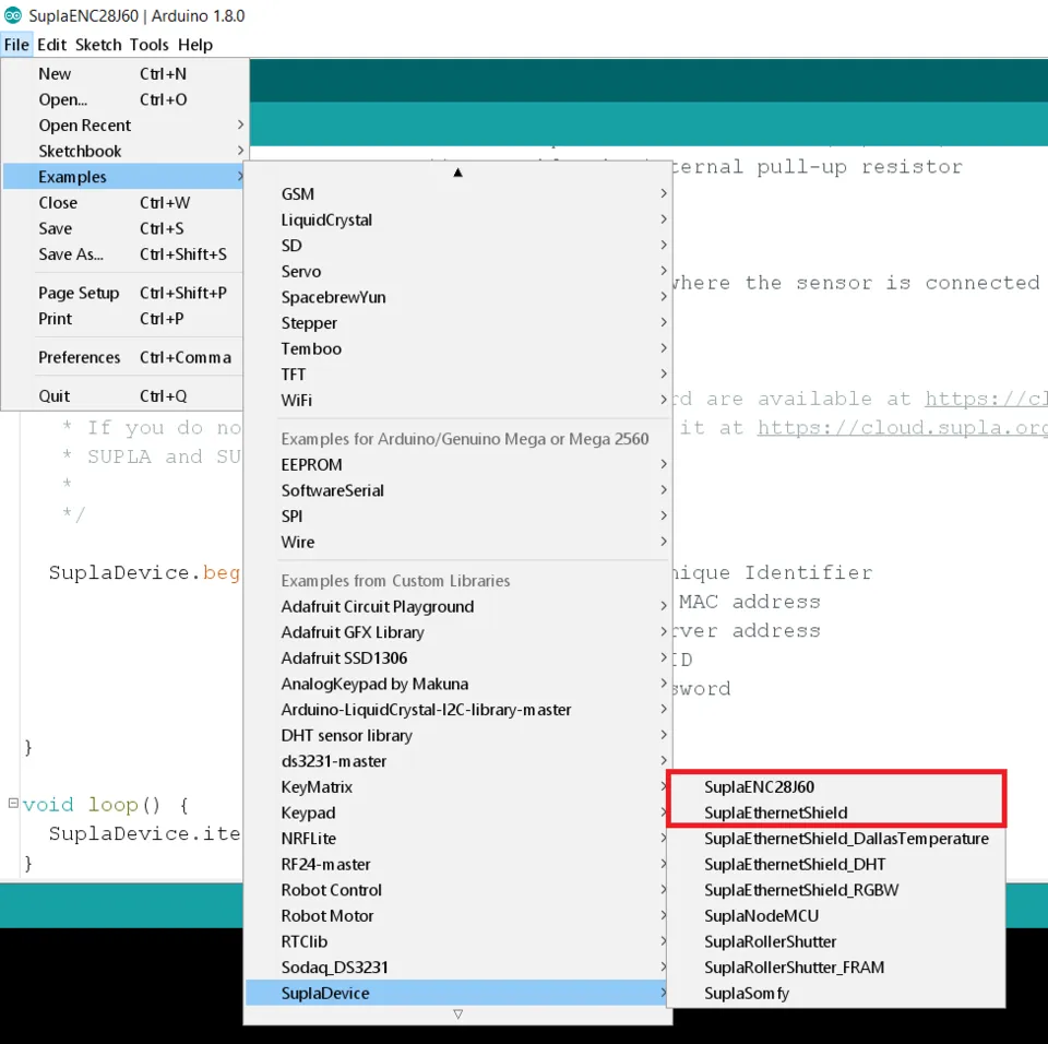
- Once you library is successfully installed, go to File -> Examples -> SuplaDevice and choose the properly example, depending on which board you use. In my case it will be ENC28J60, but next steps are the same for both boards.
- Scroll down until you see:
char GUID[SUPLA_GUID_SIZE] = {0x00,0x00,0x00,0x00,0x00,0x00,0x00,0x00,0x00,0x00,0x00,0x00,0x00,0x00,0x00,0x00};
Replace this GUID with the one you can retrieve from here. GUID is a globally unique identifier for your device. It should look like that:
char GUID[SUPLA_GUID_SIZE] = {0x69,0x0F,0x43,0x1D,0x3A,0x2D,0x54,0x2B,0x7F,0x9C,0x0B,0x03,0x07,0x1E,0x14,0x4E};
- Then you will see Ethernet MAC address. Leave it without any changes.
uint8_t mac[6] = {0x00, 0x01, 0x02, 0x03, 0x04, 0x05};
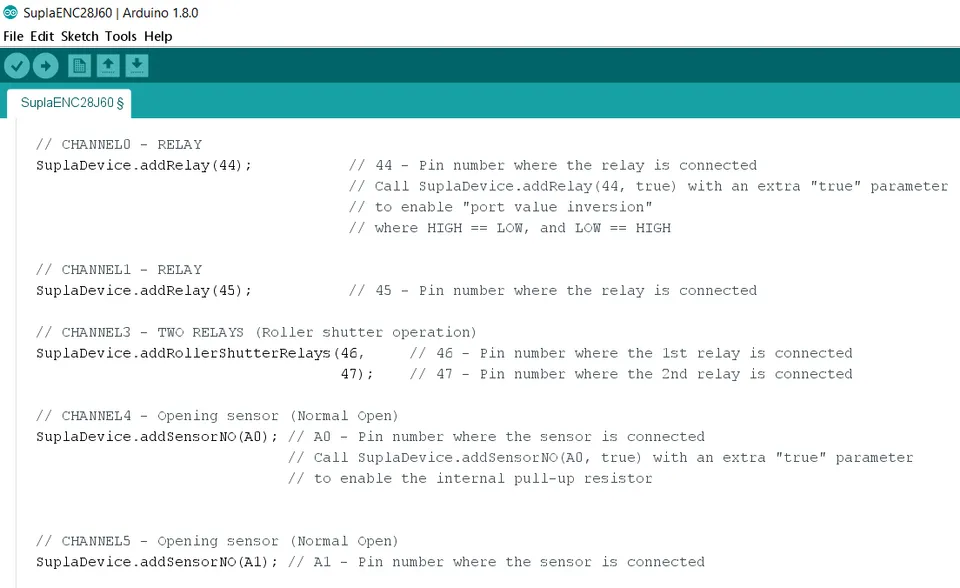
- Below you will see defined channels of your device. There are already several of them, but in this tutorial we will only take into consideration Channel 0 - Relay. Note that
(44)symbolizes the pin number where the relay is connected. You can add new relays by usingSuplaDevice.addRelay(pin number);formula.
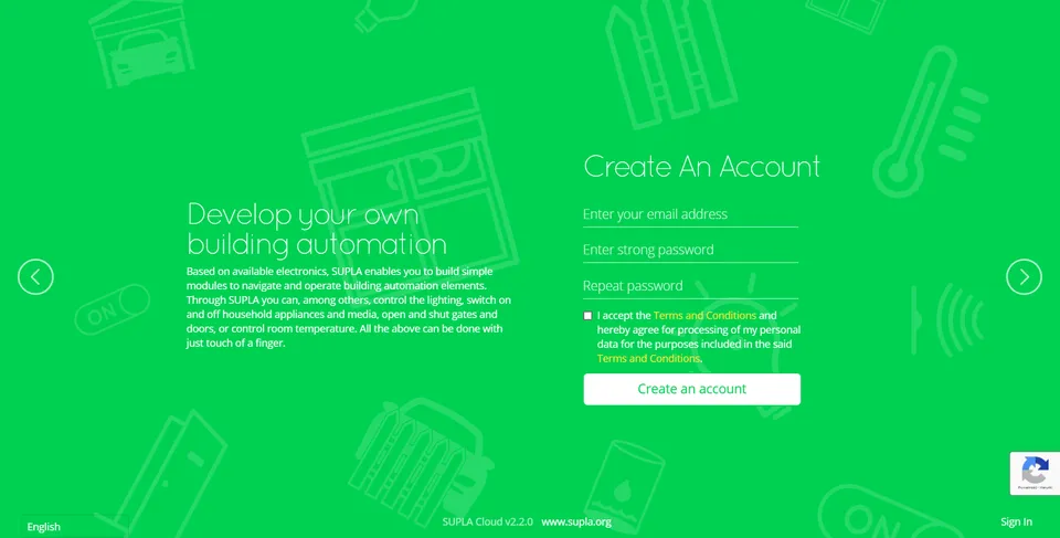
- Now, go to Supla Cloud page and create a free account by following instructions provided on the screen. Supla Cloud is a central point which connects your devices and allows you to control them via your smartphone from anywhere in the world.
- Sign in to Supla Cloud and you will get a screen with your account data. Supla-dev contains data for your control devices (in our case Arduino with relay) and supla-client contains data for your smartphone.
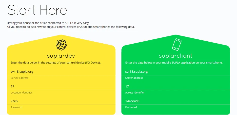
- Get back to the Arduino IDE and find your Supla Cloud configuration in the code. Fill it with data from supla-dev. In my case it looks like that:
 SuplaDevice.begin(GUID,              // Global Unique Identifier
                    mac,               // Ethernet MAC address
                    "svr18.supla.org",  // SUPLA server address
                    17,                // Location ID
                    "9ce5");           // Location Password
Upload your sketch to the Arduino. Once it is complete, reset your board.
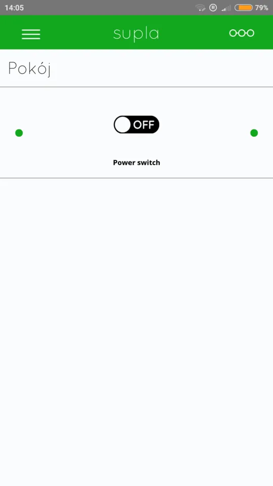
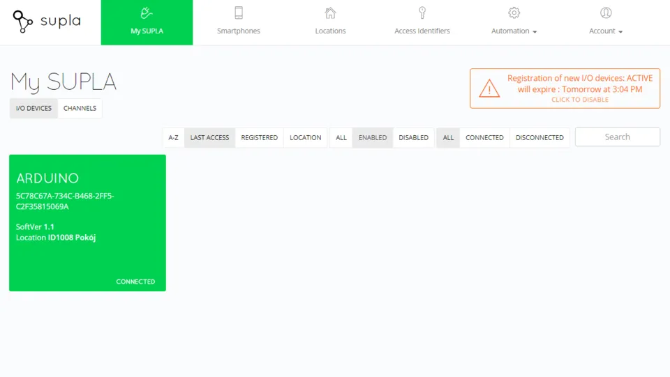
Get back to your account in Supla Cloud, and go to the My SUPLA tab. Your Arduino device should appear there as connected. Click on it and configure your relay by following instructions provided on the screen.
- Download Supla App on your iPhone or Android phone. Then open it, enter your email address and submit operation. Now you should be able to control the relay using your smartphone.