Good day everyone!
In this simple tutorial you can learn how to construct a circuit using a breadboard. So why is it so important to use breadboard in constructing a circuit? So simple, if you are not sure of the circuit’s functionality then you can try it on the breadboard. Also to avoid damaging the circuit components and to avoid hassle when the circuit is not functioning or there’s a problem in the circuit itself. In this case, we can directly troubleshoot the problems without de-soldering each component.
To start with, let us know what a breadboard is
BREADBOARD
Breadboard is an electronic tool that is being used in circuit designing and prototyping a certain project in which we can directly troubleshoot the circuit if a certain error occurs. It is commonly used in circuit testing before PCB designing.
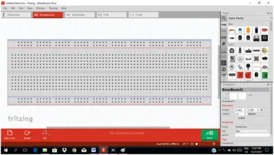
Follow these steps in constructing a circuit on the breadboard using FRITZING
Step 1: Know the connections of the breadboard
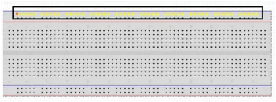
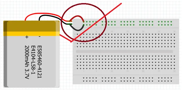
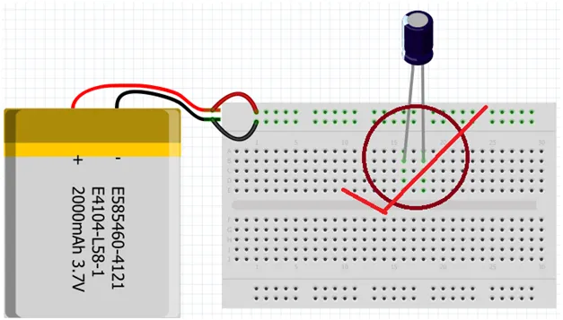
As you can see in the figure above, the two straight lines of (yellow) holes are connected. Usually these lines were used as an input, one for the ground pin and one for the other terminal. You must not put the two pins in one line alone. Like this one below.
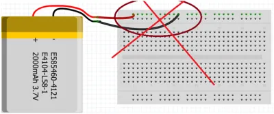
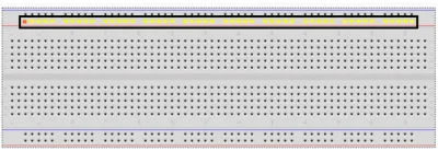
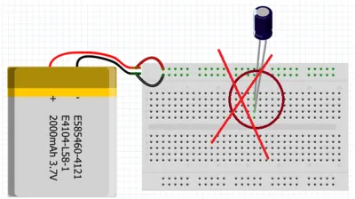
The figure below is the proper way of placing a supply for the circuit.
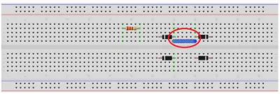
Then we have the two rows of 5 holes, in which the connection is in columns as you can see in the figure below.
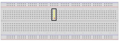
In placing electronic components, do not place pins in one column alone to avoid short circuit that could damage your circuit components.
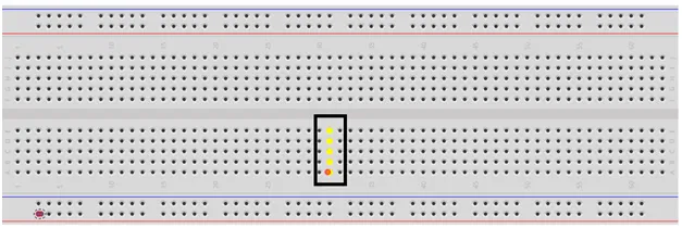
So here is the proper way.
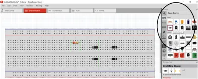
Step 2: Selection of circuit components
It is necessary to select first all the components needed for the circuit to know if it is present in the software, because not all components are present in this application. Like keypad component. Then place them in the breadboard.
Step 3: Circuit connection
After selecting all the necessary components, we can now start to construct the circuit diagram. Make sure you connect each pins correctly to avoid short circuit or else the circuit will not work properly.
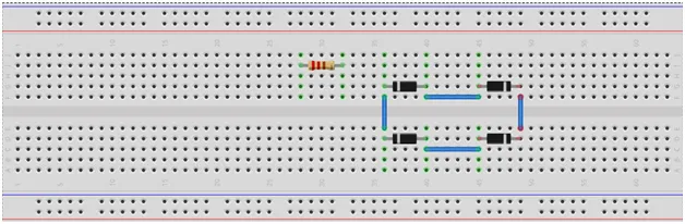
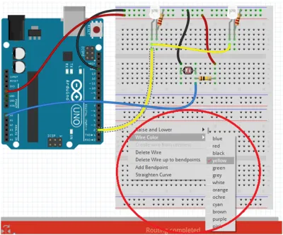
So here is a sample circuit for automatic lighting system. You can choose the wire color for color coding in the circuit connection. So after you constructed the circuit in the breadboard, you can now try to test its functionality. So that’s it, you can now design your own circuit in the breadboard.
Conclusion
In this basic tutorial, you will build the basic foundation in circuit designing in which it is very important when it comes to PCB layout. Where you can create your own circuit layout in which it will consume a small area in the printed circuit board. To avoid high costs in PCB designing much better if only small area/part of the PCB is being consumed by your design.
I Hope you find it helpful.
Yours Truly,
@rfece143
Posted on Utopian.io - Rewarding Open Source Contributors