
[Edit of Image1]
Introduction
Hey it's a me again @drifter1!
Today we continue with the Logic Design series on Verilog to get into a Sequential Logic Testbench Example.
So, without further ado, let's get straight into it!
Sequence Detector FSM
Let's implement a sequence detector.
A sequence detector outputs 1 whenever the correct sequence is inserted in the input. There are two types of such detectors:
- Overlapping
- Non-Overlapping
For example, if we want to detect 1011, then 101011 would only be detected by an overlapping detector. A non-overlapping detector would expend something of the sort 10101011. The sequence is completely reseted in an non-overlapping detector after even one wrong input.
Of course, it's possible to implement sequence detectors using Moore and Mealy FSMs. A Moore FSM will generally need at least one additional state, which is basically the output 1 state.
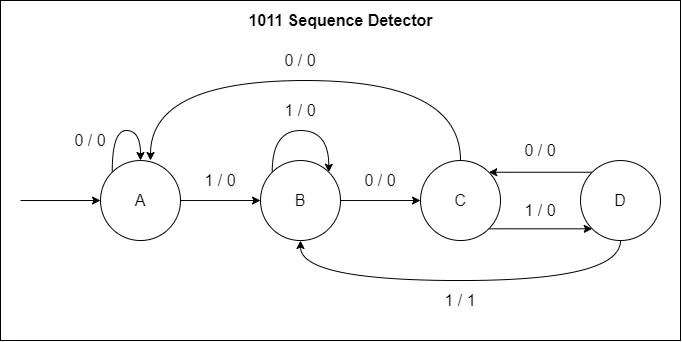
Having mentioned the 1011 sequence, let's implement such an sequence detector. Let's make it an overlapping detector and use a Mealy FSM for the implementation. I will skip the calculations, as it's a quite simple FSM. There are lots of tutorials out there for such simple things. The Mealy FSM for the 1011 Overlapping Sequence Detector is shown below.
Implementation
Let's use a single always block for the implementation.
First of all, the module's I/O consists of clk, reset and data inputs, as well as the detector output as a register. In Verilog:
module sdmo1011(output reg dout, input clk, rst, din);
    /* main module */
endmodule
There are 4 states and thus we need at least a 2-bit register for storing the state. But, let's encode the states in one-hot encoding instead, which requires 4-bits. The state definition in Verilog is:
localparam [3 : 0] A = 'b0001,
                   B = 'b0010,
                   C = 'b0100,
                   D = 'b1000;

reg [3 : 0] state;
For an asynchronous, active-low reset, the always block outline is:
always @ (posedge clk or negedge rst)
begin
    if (!rst)
    begin
        state <= A;
        dout <= 0;
    end
    else
        /* state and output logic */
end
Implementing the cases for the state and output logic is also not too difficult. What comes into the else section is simply:
case (state)
    A:
    begin
        if (din == 0)
        begin
            state <= A;
            dout <= 0;
        end
        else if (din == 1)
        begin
            state <= B;
            dout <= 0;
        end
    end
    B:
    begin
        if (din == 0)
        begin
            state <= C;
            dout <= 0;
        end
        else if (din == 1)
        begin
            state <= B;
            dout <= 0;
        end
    end
    C:
    begin
        if (din == 0)
        begin
            state <= A;
            dout <= 0;
        end
        else if (din == 1)
        begin
            state <= D;
            dout <= 0;
        end
    end
    D:
    begin
        if (din == 0)
        begin
            state <= C;
            dout <= 0;
        end
        else if (din == 1)
        begin
            state <= B;
            dout <= 1;
        end
    end
endcase
Testbench
The testbench sdmo1011_tb needs three registers for the three inputs and one wire for the output. Whilst, the module can be instantiated and mapped easily using positional mapping, as shown below.
module sdmo1011_tb;

  reg din, clk, rst;
  wire dout;

  sdmo1011 UUT (dout, clk, rst, din);

  /* test cases */

endmodule
The clock requires a generator, and in order to use EDA Playground later we also need the $dumpfile, $dumpvars and $finishsystem tasks. Thus, the main outline of the test cases is:
initial begin
    $dumpfile("dump.vcd");
    $dumpvars;
    clk = 0;
    rst = 1;
    din = 0;

    /* reset */

    /* input sequence */

    $finish;
end

always begin
    #1 clk = ! clk;
end
Resetting the FSM is as simple as:
#2;
rst = 0;
#2;
rst = 1;
and let's input the 101011 sequence from before and output to the console if it's detected correctly:
din = 1;
#2;

din = 0;
#2;

din = 1;
#2;

din = 0;
#2;

din = 1;
#2;

din = 1;
#2;

if (dout == 1)
    $display("Detected 1011!");
Simulation using EDA Playground
In EDA Playground we simply have to copy-and-paste the Verilog code.
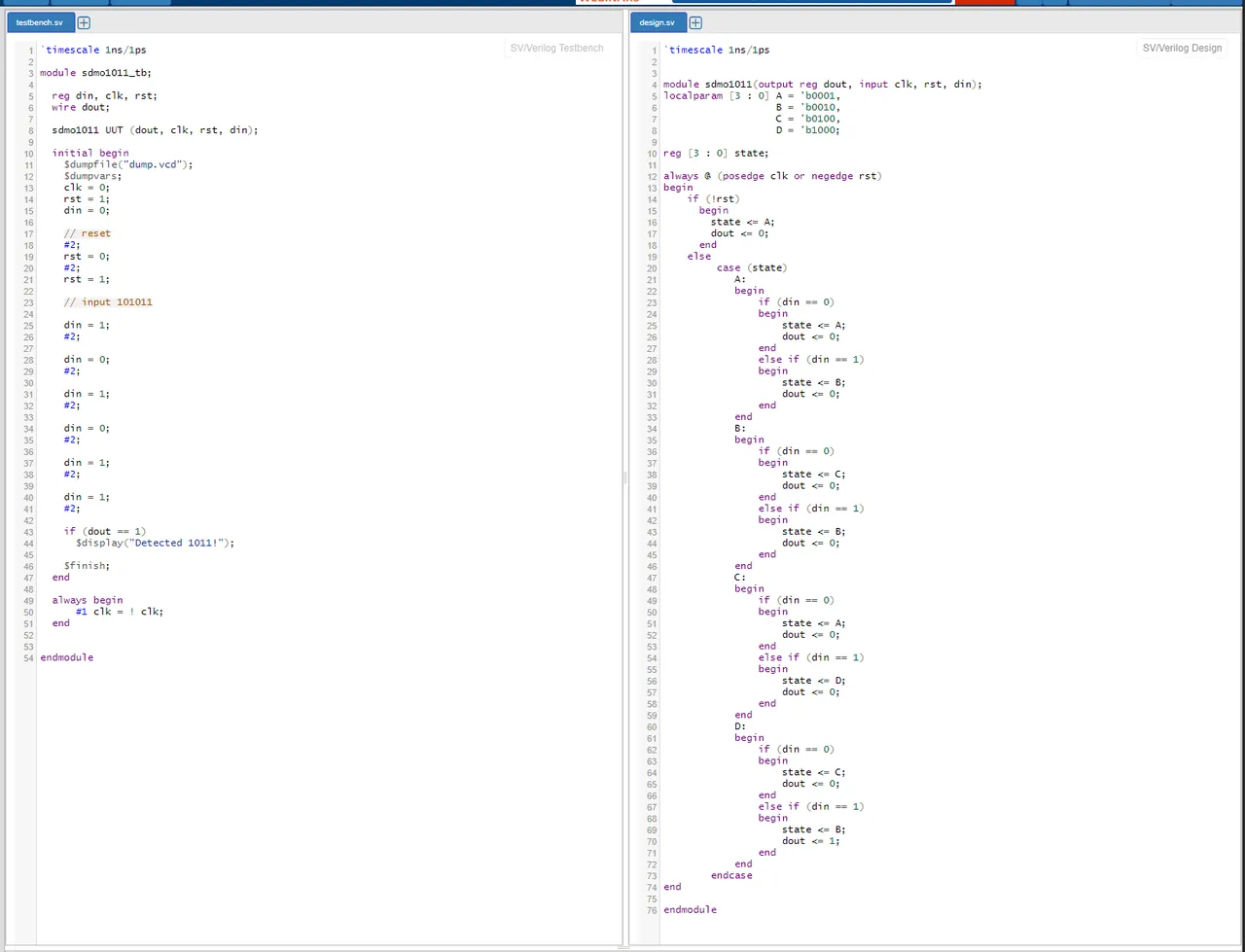
Let's choose Icarus Verilog as the compiler and tick the Open EPWave after run box. Afterwards, clicking Run yields the following waveform:
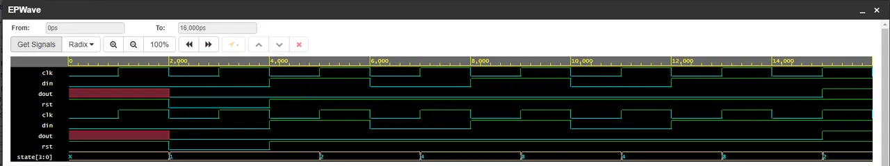
and console output:
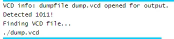
In other words, the sequence was correctly detected!
Looking at the waveform we can identify the state transitions that occurred, which are:
→ A → B → C → D → C → D → B
RESOURCES:
References
- http://www.asic-world.com/verilog/veritut.html
- https://www.chipverify.com/verilog/verilog-tutorial
- https://www.javatpoint.com/verilog
Images
Block diagrams and other visualizations were made using draw.io
Previous articles of the series
- Introduction → Basic Syntax, Data Types, Operators, Modules
- Combinational Logic → Assign Statement, Always Block, Control Blocks, Gate-Level Modeling and Primitives, User-Defined Primitives
- Combinational Logic Examples → One Circuit - Four Implementations, Encoder, Decoder, Multiplexer
- Sequential Logic → Procedural Blocks (Initial, Always), Blocking and Non-Blocking Assignments, Statement Groups
- Sequential Logic Examples → Flip Flops (DFF, TFF, JKFF, SRFF), N-bit Counter, Single-Port RAM
- Finite-State Machines → Finite-State Machine (FSM), FSM Types, State Encoding, Modeling FSMs in Verilog
- Finite-State Machine Examples → Moore FSM Example (1 and 2 always blocks), Mealy FSM Example (1, 2 and 3 always blocks)
- Testbenches and Simulation → Testbenches (DUT / UUT, Syntax, Test Cases), System Tasks, Simulation Tools
- Combinational Logic Testbench Example → Half Adder Implementation, Testbench and Simulation
Final words | Next up
And this is actually it for today's post!
In the next articles of the series, we will either start getting into more advanced examples, or start covering SystemVerilog and the additional blocks that it provides...
See Ya!

Keep on drifting!