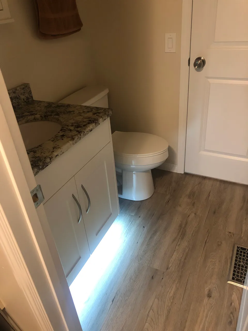
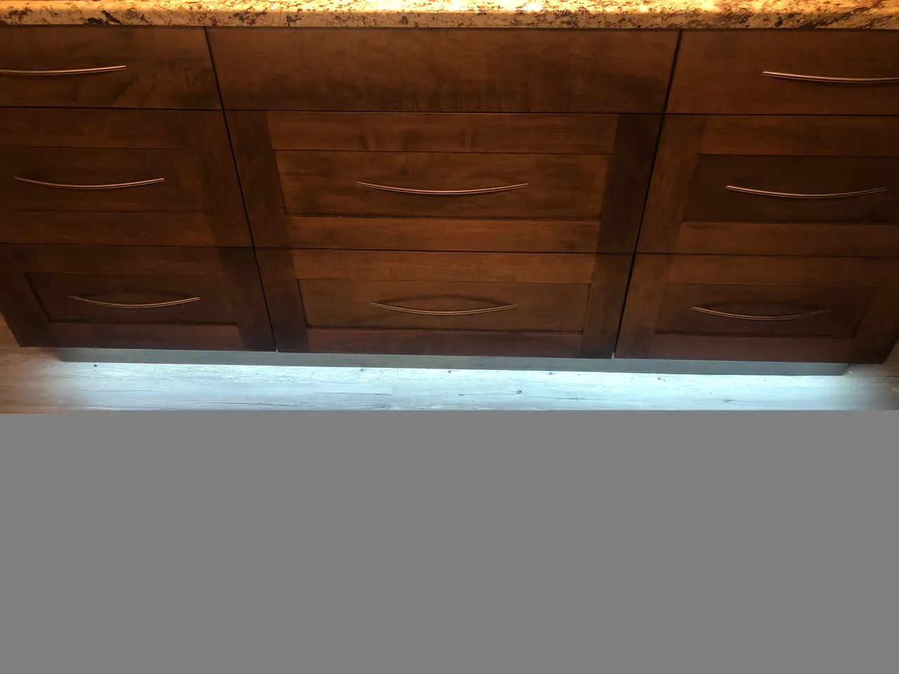
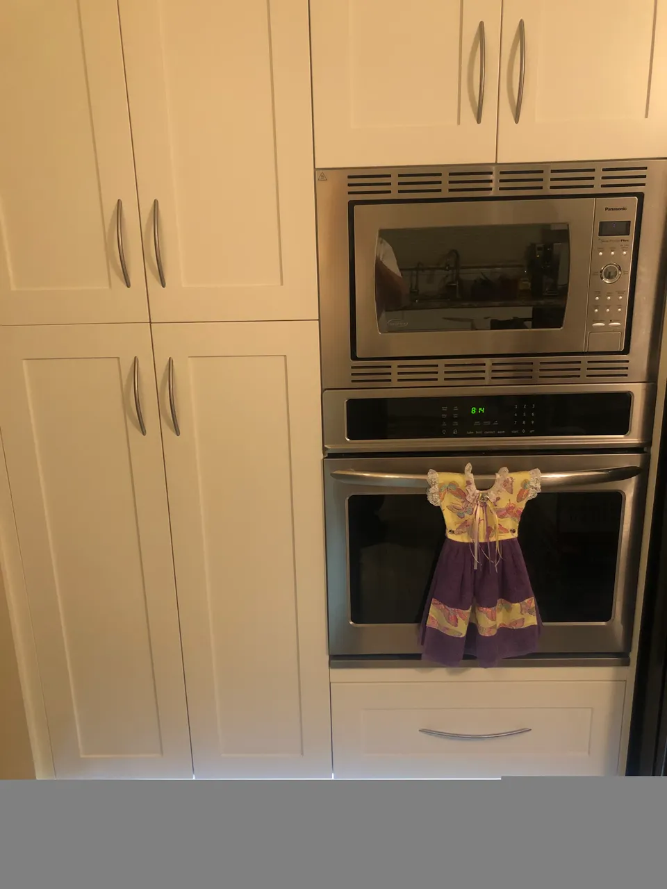
In my first post I went over the layout of my Raspberry Pi home automation system. In my second post I went into a little bit more detail on the Power Supply and Raspberry Pi. In my third post I described my MOSFET controller board that I used to control the LED light strips that I have installed in the toe kick area of my kitchen and bathroom cupboards. Here are a couple of pics of the lights in action;
So the MOSFET board is great at turning the 5V or 12V from the power supply on or off to a device such as the LED lights. The MOSFET's could also be used to dim the LED lights via PWM (Pulse Width Modulation) from the Pi.
But what if you want to control a different device that has a separate power source not connected to your raspberry pi? That is where I use these small relays:
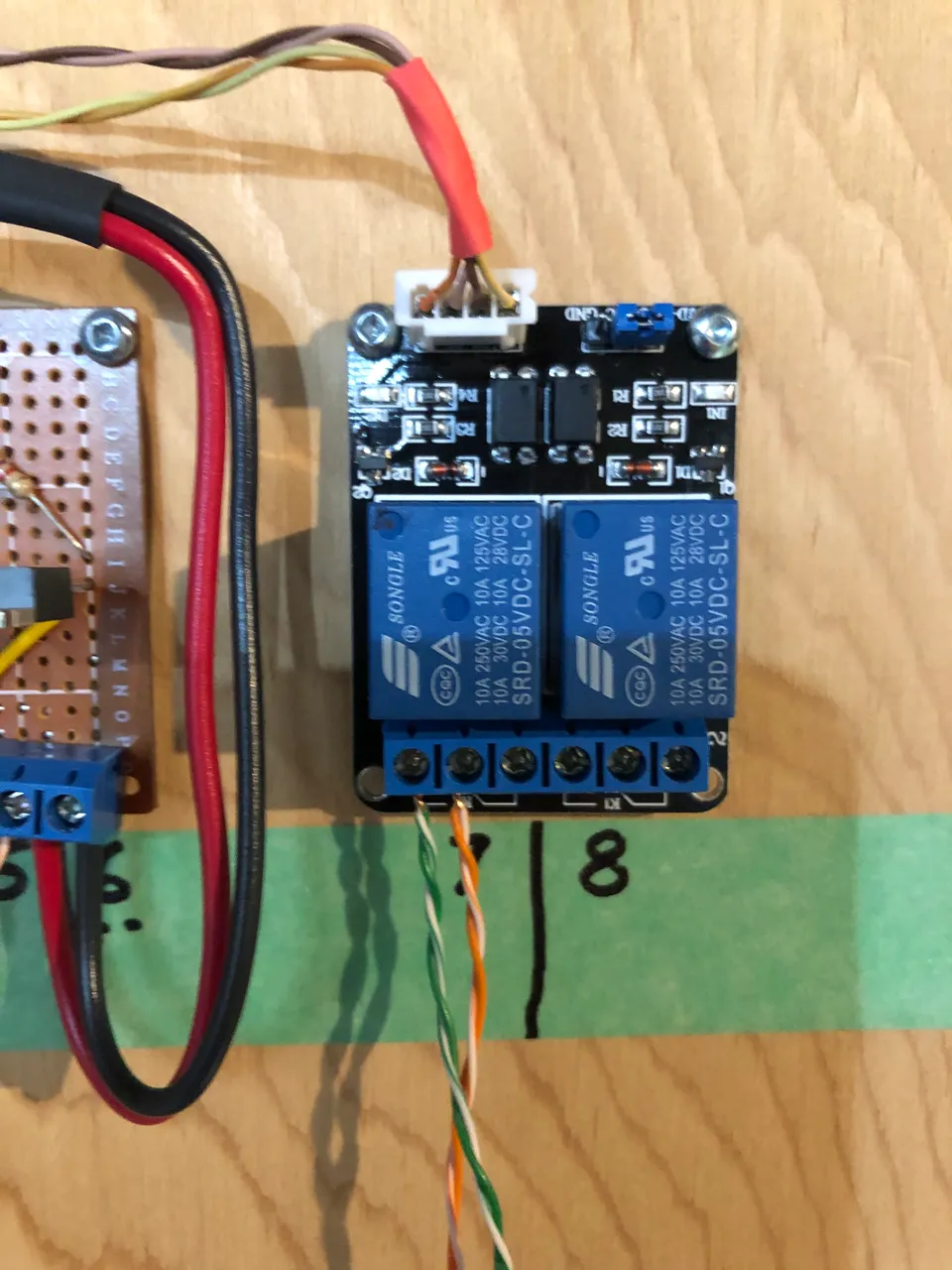
In Canada we use a forced air furnace to heat the house in the winter, and our hobby room is downstairs where it is a little cooler. So the solution is to turn the furnace fan on to circulate the warm air more evenly throughout the house. The circuit board in the furnace has a set of contacts that when shorted out (with a switch) will turn the fan on, and I'm using this relay as a remote controlled switch! The orange and green wires you see coming out of the bottom of the relay board are connected to the NO (Normally Open) contacts on the relay and to the Fan Override contacts on the furnace circuit board. The second relay (#8) is a spare for future use.
Previously, I showed how I used MOSFET's to isolate and amplify the outputs of the Raspberry Pi. The small black IC's (Integrated Circuits) above the blue relays are opto-isolators which perform a similar function. They optically (via a LED & opto-coupler inside) isolate the output from the Pi GPIO pin from the relay coil. They are great, but they don't handle much current, so I couldn't use them to drive my LED light strips. I purchased these relay boards from ebay.ca and I've seen them as single, double, quad and even 8 relay boards.
***** One word of warning, be very, very skeptical of the ratings on the top of the blue relays (grin). 10A @ 250V or 125VAC. I have found them to work great with small current loads up to a couple of amps, but I tried to use one to control a 500W halogen lamp ~4A and it worked great for about a month, and then the contacts burned out. In a later post I'll show you a circuit I built where the Pi controls a set of small blue relays, and they in turn control a much larger set of relays to a much higher current load.
In tomorrow's post, I'll go over the Node-Red software I'm using in the Pi and hopefully show you how easy it is to be able to remotely control these devices from your smartphone, or tablet!
Thanks for viewing!
Robin